Numerical control bevel gear rolling inspection machine

A technology for inspecting machines and bevel gears, which is applied in the direction of machine gear/transmission mechanism testing, power measurement, and measuring devices. It can solve problems such as high labor intensity, inaccurate detection results of gear movement, and difficult observation of detection results, and achieve labor intensity. Accurate and reliable results of small and gear pair motion detection results

Inactive Publication Date: 2008-04-16
TIANJIN NO 1 MACHINE TOOL WORKS
View PDF0 Cites 16 Cited by
  • Summary
  • Abstract
  • Description
  • Claims
  • Application Information

AI Technical Summary

Problems solved by technology

[0003] The above-mentioned prior art bevel gear pair motion quality inspection machine tool has the following defects: 1. The gear motion detection result is inaccurate
2. The measurem

Method used


Image

  • Numerical control bevel gear rolling inspection machine
  • Numerical control bevel gear rolling inspection machine
  • Numerical control bevel gear rolling inspection machine

Examples


Embodiment Construction

[0043] Embodiments of the present invention will be further described below in conjunction with the accompanying drawings.

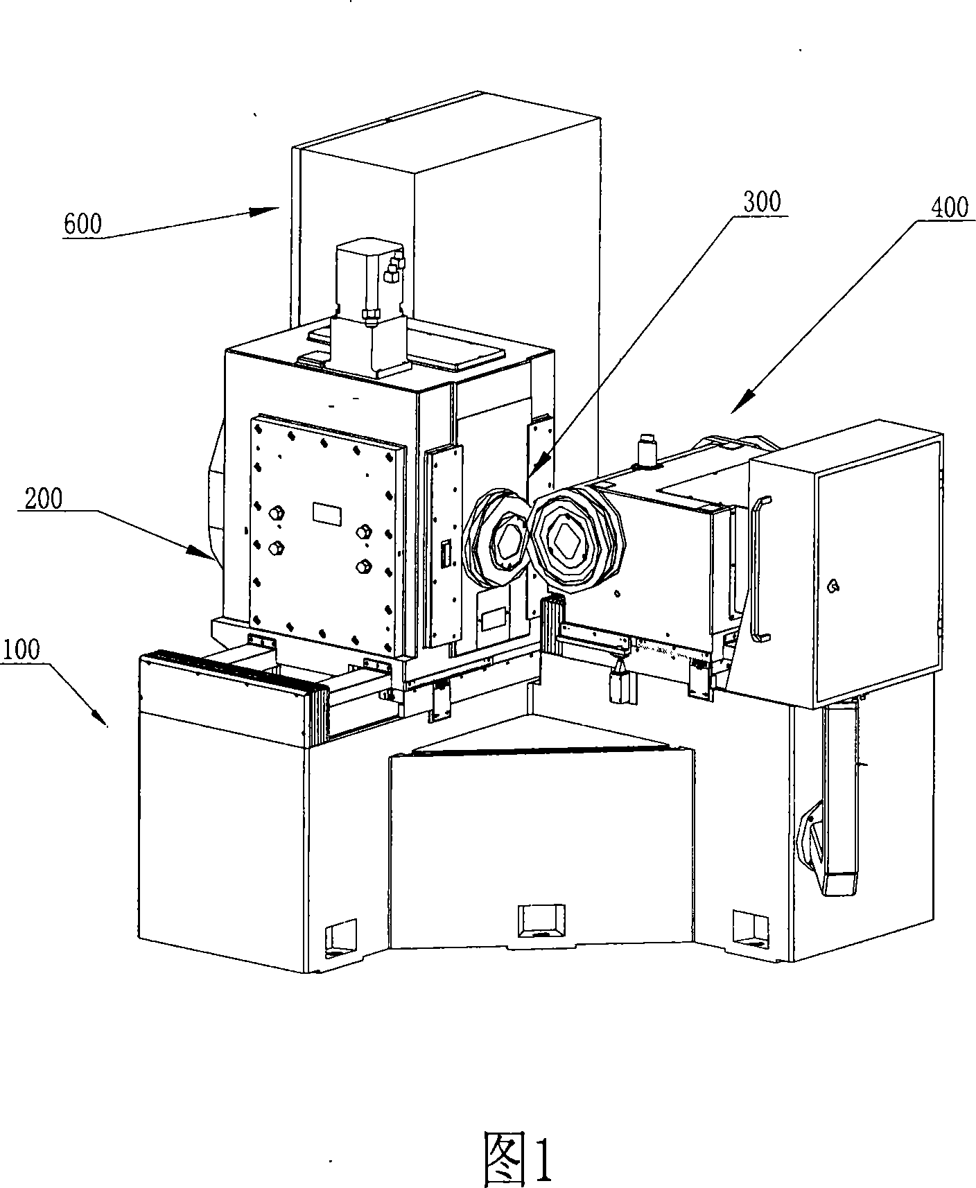
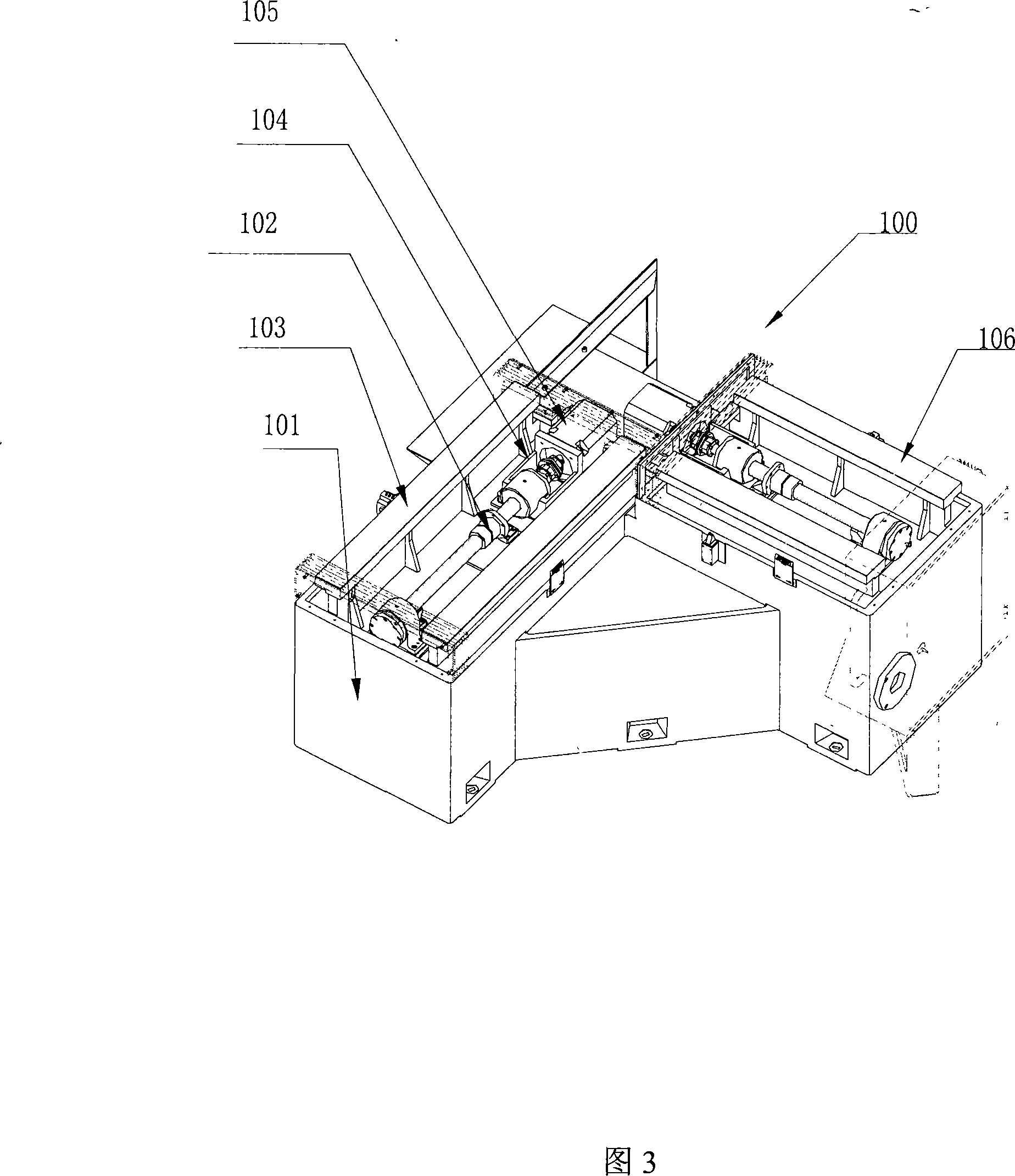
[0044] The present invention provides a numerically controlled bevel gear rolling inspection machine, which includes: a bed part 100 , a column part 200 , a driving box part 400 , a driven box part 300 and an electrical control part 600 . On the bed part 100, a driving guide rail 106 and a driven guide rail 103 which are 90° to each other are arranged respectively. The column part 200 is arranged on the driven guide rail 103 of the bed 101, the active box part 400 is arranged on the active guide rail 106 of the bed 101, between the bottom of the column part 200 and the active box part 400 and the bed 101 respectively An automatic moving mechanism that moves along the driven guide rail 103 and the active guide rail 106 is provided; the driven box part 300 is arranged in the column part 200 and has a mechanism that can automatically move along the vertical...


PUM


Abstract

The invention discloses a numerical control bevel roll tester, the structure of the invention comprises: a lathe bed respectively provided with a drive guide rail and a driven guide rail which are perpendicular to each other, an upright post arranged on the driven guide rail of the lathe bed, a driving headstock arranged on the drive guide rail of the lathe bed, automatic travel mechanisms which are respectively arranged between the bottom of the upright post and the lathe bed and between the bottom of the driving headstock and the lathe bed, and a driven headstock which is arranged in the upright post and provided with an automatic travel mechanism which can move in vertical direction. The driving headstock and the driven headstock are respectively provided with a drive main shaft and a driven main shaft which are perpendicular to each other and positioned horizontally, a gear pair to be tested is respectively arranged in the inner holes of the drive main shaft and the driven main shaft; the drive main shaft is connected with a drive mechanism which drives the drive main shaft to rotate. The invention has the advantages that: the automatic aligning teeth, the autoloading and torque display, the automatic measurement and the automatic test according to the preset programs in the rolling test process of the bevel gear pair are solved, and precise parameters are provided for the cutting machine modifying gear cutting parameters.

Description

technical field [0001] The invention relates to a machine tool for inspecting the motion quality of a bevel gear pair, in particular to a numerically controlled bevel gear rolling inspection machine. Background technique [0002] The bevel gear motion quality inspection machine tool in the prior art mainly includes: a bed part, a guide rail, a driving box part, a driven box part, a loading device, and an electrical control part; the driving box part is equipped with a driving spindle, The detected driving bevel gear is installed in the hole of the driving main shaft; the driven box part is equipped with the driven main shaft, and the detected driven bevel gear is installed in the hole of the driven main shaft. When testing the bevel gear pair, the above-mentioned driving box part and driven box part need to move on the guide rail of the bed part. In the prior art, there are two ways to move the guide rails of the active box part and the driven box part on the bed part: 1. m...

Claims


Application Information

Patent Timeline
IPC IPC(8): G01M13/02G01L3/00
Inventor 祁志良
Owner TIANJIN NO 1 MACHINE TOOL WORKS
Why Eureka
Try Eureka