Series battery charge up circuit with charge compensate function

A technology of connecting battery packs and charging circuits in series, which is used in the charging control of large-capacity power batteries, and electrical appliance control. Achieve the effect of improving charging and discharging efficiency and improving power conversion efficiency

Inactive Publication Date: 2008-04-16
赵建和
View PDF1 Cites 15 Cited by
  • Summary
  • Abstract
  • Description
  • Claims
  • Application Information

AI Technical Summary

Problems solved by technology

Due to the control accuracy of the production process, there are differences in the various electrochemical parameters of each single battery, making it difficult to achieve complete consistency in the capacity, charge and discharge characteristics, and initial state of the single battery
Using a well-known method to connect multiple single cells in series to form a battery pack. After the power battery is made, the characteristics and initial state differences of each battery are retained in the battery pack. During the charging and discharging process, each unit in the battery pack The current passed by the bulk battery is the same. Due to the differences in the characteristics and initial states of each battery, the charging capacity of each battery cannot be fully utilized, which reduces the charging and discharging efficiency of the battery pack or power battery. The more serious situation is , with the continuous increase of charging-discharging times in use, the differences in the state, charging / discharging characteristics and charging capacity of each battery that make up the battery pack will gradually increase, resulting in some batteries being "overcharged" during charging, and some batteries being "overcharged" during discharging. Battery "over-discharged"
Both "overcharging" and "overdischarging" will cause irreversible damage to the battery. The damaged battery will generate a lot of heat during the subsequent charging and discharging process, which will seriously affect the overall discharge efficiency and service life of the power battery, and will also bring serious damage to the charging and discharging process. Security risks
[0003] Chinese patent ZL00137155.X discloses a circuit scheme for controlling the charging and discharging of a battery pack in series, which connects the batteries that make up the battery pack in series, and detects the voltage, temperature and current of the battery pack in real time during the charging and discharging process , take the method of reducing charging power or discharging power to protect each battery in the battery pack, which can effectively prevent the battery from "overcharging", "over-discharging" and "overheating", but it cannot compensate for the individual batteries that make up the battery pack in series. Due to the difference in initial state and the difference in charging / discharging characteristics, the charging capacity of each battery cannot be fully utilized, which reduces the charging and discharging efficiency of the battery pack or power battery
For a large-capacity power battery pack, the charging current is large. In order to make the equalization circuit work effectively, its power dissipation must be increased, resulting in a large amount of heat, resulting in energy waste and low charging efficiency.
In order to meet the heat dissipation requirements, the control equipment is huge

Method used


Image

  • Series battery charge up circuit with charge compensate function
  • Series battery charge up circuit with charge compensate function

Examples


Embodiment approach

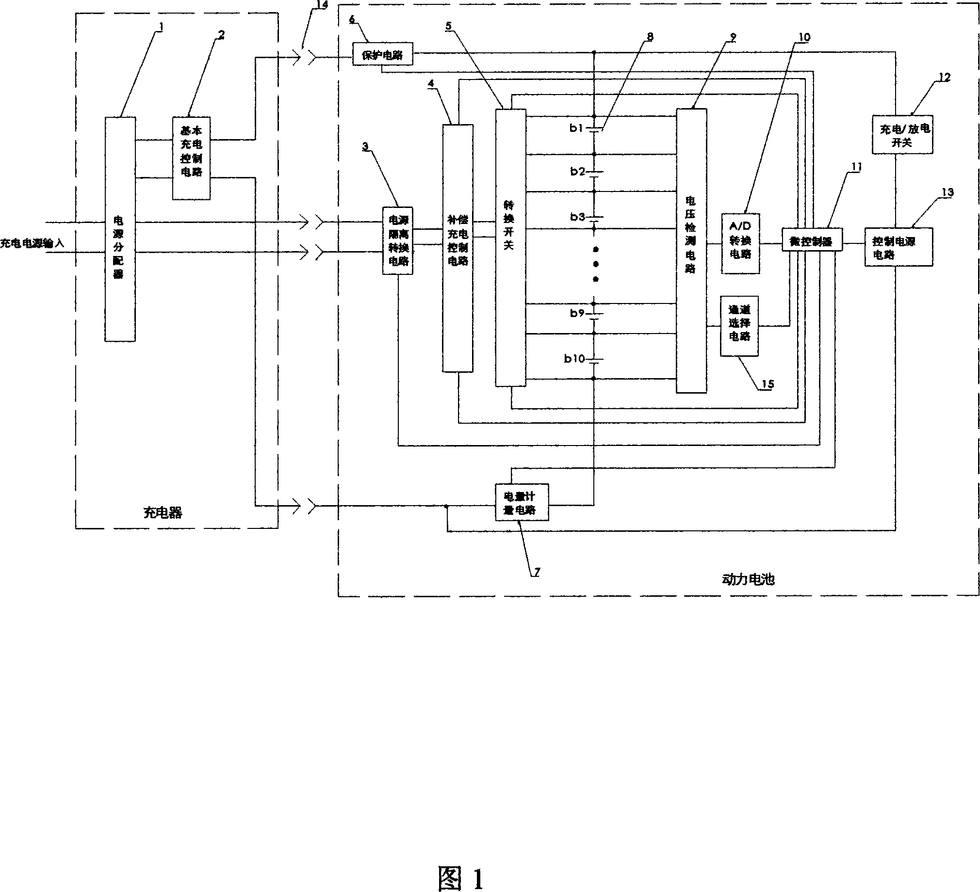
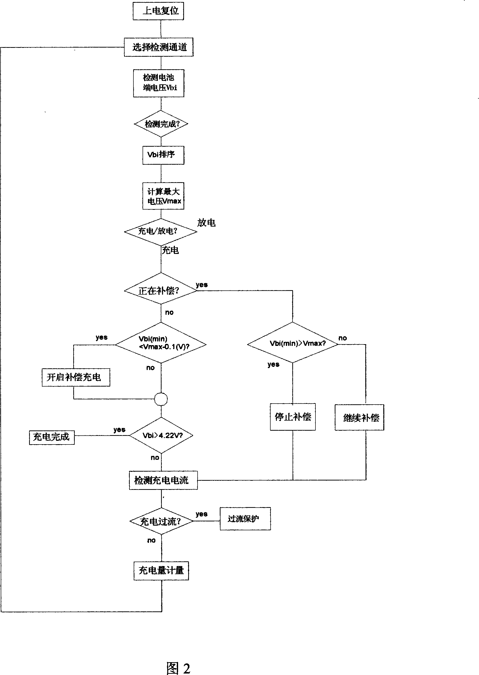
[0022] The implementation method is as follows, see Figure 1 and Figure 2:

[0023] (1) The power distributor 1 adopts a copper connection terminal with a capacity of 5A, and supplies the input power to the basic charging control circuit 2 and the power isolation conversion circuit 3 respectively.

[0024] (2) The basic charging control circuit 2 is composed of an AC / DC converter of AC220V / DC48V15A and a high-power field effect transistor MTB30P06 to form a constant current control circuit to provide a basic charging current of 10A to the series battery pack 8 .

[0025] (3) The power isolation conversion circuit 3 uses an AC200V / 5V20W power isolation transformer and a 5A bridge full-wave rectification circuit to convert the AC220V charging power into a suspended DC5V DC power supply.

[0026] (4) Compensation charging control circuit 4 uses field effect transistor NTMS10P02 as a constant current control element, and the output current is constant at 2A.

[0027] (5) The tran...


PUM


Abstract

The present invention provides a charging control circuit which can compensate the charging for battery with lower voltage in series battery set during charging and enables the terminal voltage of independent battery in series battery set to tend to uniform. The charging control circuit can detect the terminal voltage of the independent battery in series battery set in real time during charging and compensate charging for the battery with lower terminal voltages through a compensation charging circuit, thereby making up the differences of the initial state and the charging/discharging characteristics for independent battery in the battery set, unleashing the loading capability of the independent battery while making sure the independent battery has no over-charging and improving charging and discharging efficacy of the power battery.

Description

Technical field [0001] The invention relates to a circuit for controlling the charging of series battery packs, in particular to controlling the charging of large-capacity power batteries, which belongs to the electrical control category. Background technique [0002] The power battery is the power source for electric loads such as electric tools, electric vehicles, electric bicycles, and emergency lighting. The power battery is a battery pack composed of multiple single cells in series. The higher the voltage, the more the number of single cells that need to be connected in series. Due to the control accuracy of the production process, there are differences in the various electrochemical parameters of each single battery, making it difficult to achieve complete consistency in the capacity, charge and discharge characteristics, and initial state of the single battery. Using a well-known method to connect multiple single cells in series to form a battery pack. After the powe...

Claims


Application Information

Patent Timeline
Patent Type & Authority Applications(China)
IPC IPC(8): H02J7/00H01M10/44
CPCY02E60/12Y02E60/10
Inventor 赵建和
Owner 赵建和
Why Eureka
Try Eureka