Optical processing structure for digital optical processing projection device

A technology of digital light processing and projection device, which is applied to the image reproducer of projection device, projection device, optics, etc., can solve the problems of increasing difficulty in lens design, back focal length of projection objective lens, and large prism volume.

Inactive Publication Date: 2008-04-23
DELTA ELECTRONICS INC
View PDF0 Cites 10 Cited by
  • Summary
  • Abstract
  • Description
  • Claims
  • Application Information

AI Technical Summary

Problems solved by technology

Because this system uses a beam splitting prism for both light splitting and light combining, the prism is larger in size and heavier in weight, and the back focus of the projection objective lens required is also longer, making the design of the lens more difficult.

Method used


Image

  • Optical processing structure for digital optical processing projection device
  • Optical processing structure for digital optical processing projection device
  • Optical processing structure for digital optical processing projection device

Examples


Embodiment Construction

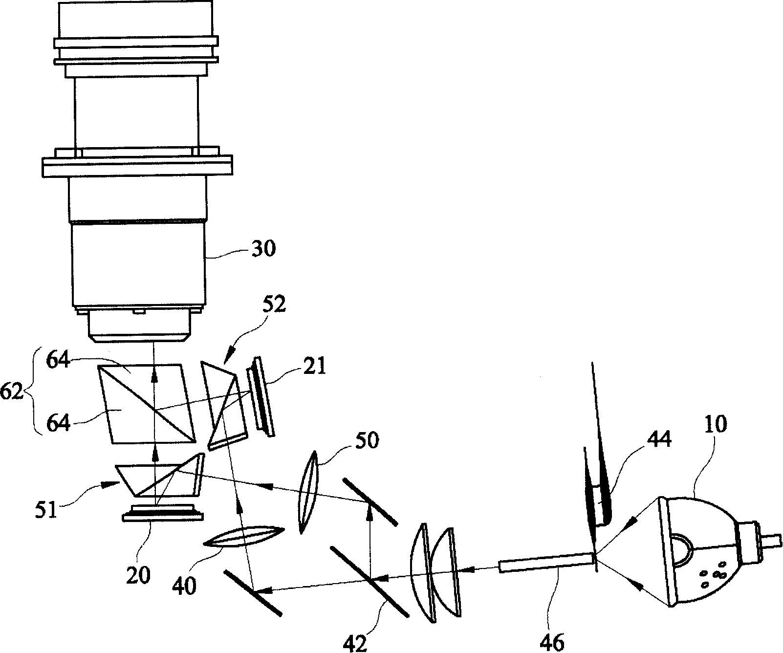
[0038] figure 2 Represents one embodiment of the light processing structure used in the digital light processing projection device of the present invention, wherein the DLP projection device includes a light source 10, a plurality of digital micromirror devices (two digital micromirror devices 20, 21 are shown in the figure) , the projection objective lens 30 and the light processing structure of the present invention. The light processing structure includes a light splitting structure, a reflection structure and a light combining structure.

[0039] In detail, the light splitting structure includes at least one light splitting component for splitting the main incident light emitted by the light source 10 into a plurality of secondary incident lights. In a specific embodiment, the beam splitting component can be a beam splitter 42. According to different light source types and different beam splitting requirements, the beam splitting coating in the beam splitter is used to s...


PUM


Abstract

The DLP projecting apparatus comprises multi digital micro lens devices. Said optic processing structure comprises: a spectrum architecture, a reflection architecture and a beam-combining architecture; the spectrum architecture uses the beam splitter and color wheel to splitting the beams; the reflection architecture comprises multi reflection prisms corresponding to said multi digital micro lens devices; the beam-combining architecture is composed of two triangle prisms.

Description

technical field [0001] The present invention relates to a light processing structure for a digital light processing (DLP) projection device, and more particularly to a light processing structure for a DLP projection device with a multiple digital micromirror device (DMD) architecture. Background technique [0002] figure 1 It is a schematic diagram of a digital optical processing projection device in Taiwan Patent Application No. 93101928. The case was filed by the applicant of this case on January 29, 2004. The digital optical processing projection device is mainly composed of a coupling module (Coupling Module) 200, a light source 300, a light splitting module (Splitting Module) 400, three digital micromirror devices 500R, 500G, 500B, and a projection objective lens (Project Lens) 600. . [0003] The light source 300 emits light W to the light splitting module 400 through an integration rod (Integration Rod) 310 . The light splitting module 400 splits the light W into ...

Claims


Application Information

Patent Timeline
Patent Type & Authority Applications(China)
IPC IPC(8): G02B27/10G03B21/14H04N9/31
Inventor 陈锡钊黄俊杰
Owner DELTA ELECTRONICS INC
Why Eureka
Try Eureka