High-power double burner for gas cookers, with multiple concentric flame crowns

A dual-combustion, flame furnace technology, applied in the direction of gas fuel burners, burners, combustion methods, etc.

Active Publication Date: 2008-04-23
SOMIPRESS SOC METALLI INIETTATI
View PDF0 Cites 13 Cited by
  • Summary
  • Abstract
  • Description
  • Claims
  • Application Information

AI Technical Summary

Problems solved by technology

This is because the limited burner height prevents the length of the Venturi chamber with the vertical axis of the peripheral burner to extend

Method used


Image

  • High-power double burner for gas cookers, with multiple concentric flame crowns
  • High-power double burner for gas cookers, with multiple concentric flame crowns
  • High-power double burner for gas cookers, with multiple concentric flame crowns

Examples


Embodiment Construction

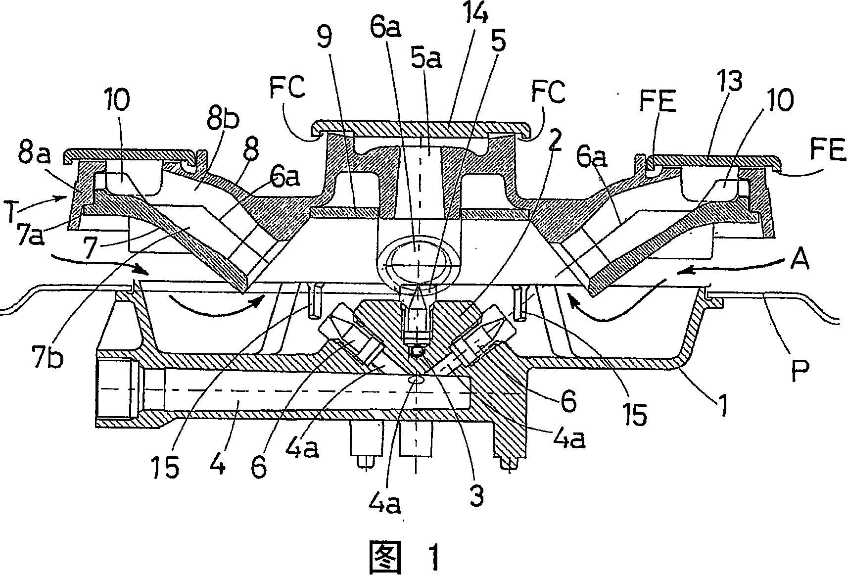
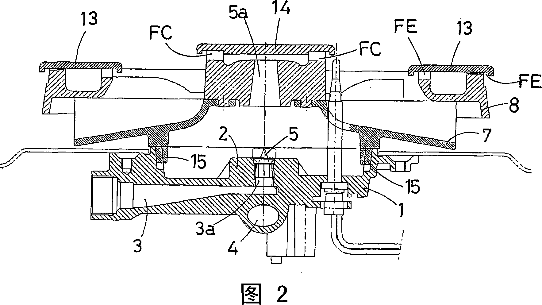
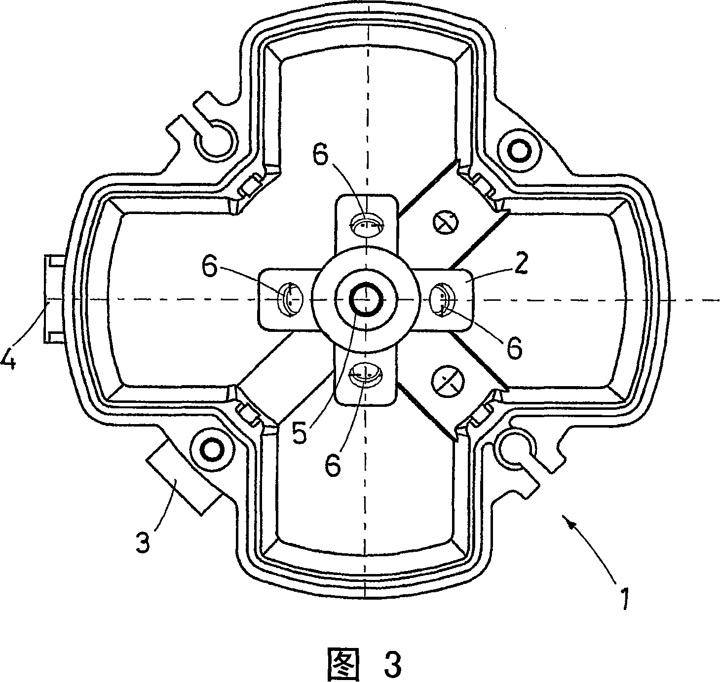
[0026] With reference to the above figures, the double burner of the present invention comprises a circular basin-shaped body 1 housing a raised central crosspiece 2 on which there are housings for a plurality of gas nozzles.

[0027] The main body 1 generally houses two distinct and disconnected gas inlet ducts 3 and 4, each of which can selectively and separately feed the nozzles connected to the centrally fired crown and the nozzles connected to the peripheral fired crown Group.

[0028] The two gas inlet ducts 3 and 4 reach the center of the body 1 at slightly different heights; more precisely, the upper inlet duct 3 ends exactly in the center of the body 1, while the lower inlet duct 4 passes above the center, as shown in Fig. 1.

[0029] A vertical channel 3a branching upwards from the upper gas inlet duct 3, on which is mounted a first nozzle 5 designed to introduce the gas into the venturi mixing chamber that feeds the central flame crown FC; at the same time, Branch...


PUM


Abstract

The present invention refers to a double burner for gas cookers with multiple concentric flames, characterized by high power and compact height, which comprises five Venturi mixing chambers, i.e. one central chamber (5a) with vertical axis that feeds the central burner and four regularly spaced chambers (6a) with inclined axis that feed the external annular burner.

Description

technical field [0001] The patent application for this industrial invention relates to a double burner for a gas stove with a multi-circle concentric flame crown, characterized by high power and small height. Background technique [0002] The term "twin burner" means that the burner comprises two different gas inlet pipes with corresponding rotary valves, which respectively feed two or more concentric flame crowns, which can be selectively opened or Closed, can be fed autonomously through two channels originating from said split pair of intake ducts. [0003] Despite the multi-circle concentric flame crown, the traditional burner is characterized by only one gas inlet pipe with corresponding rotary valve, which supplies all the channels for supplying the air-gas mixture to the burner head . [0004] This means that with conventional burners the concentric flame crowns are always on and off at the same time, however, in the case of dual burners the user can decide to open a...

Claims


Application Information

Patent Timeline
Patent Type & Authority Applications(China)
IPC IPC(8): F23D14/06
CPCF23D2900/14062F23D14/065B22D17/00
Inventor 皮耶罗·阿尔曼尼
Owner SOMIPRESS SOC METALLI INIETTATI
Why Eureka
Try Eureka