Data collection device and gateway device

A technology of data collection and collection unit, applied in the direction of instruments, electrical testing/monitoring, control/regulation systems, etc., it can solve the problems such as troublesome calculation and setting of thresholds, time-consuming device debugging, and inability to use actual operation, etc., to reduce the thresholds or condition hassle, reduce time, reduce the effect of setting wrong thresholds or conditions

Inactive Publication Date: 2008-04-23
MITSUBISHI ELECTRIC CORP
View PDF1 Cites 14 Cited by
  • Summary
  • Abstract
  • Description
  • Claims
  • Application Information

AI Technical Summary

Problems solved by technology

[0006] In addition, in the trial operation for setting the threshold, abnormal state detection cannot be performed, and it cannot be used in actual operation, so there is troublesome calculation and setting of the threshold, and there is a problem that it takes time to debug the device

Method used


Image

  • Data collection device and gateway device
  • Data collection device and gateway device
  • Data collection device and gateway device

Examples


Embodiment 1

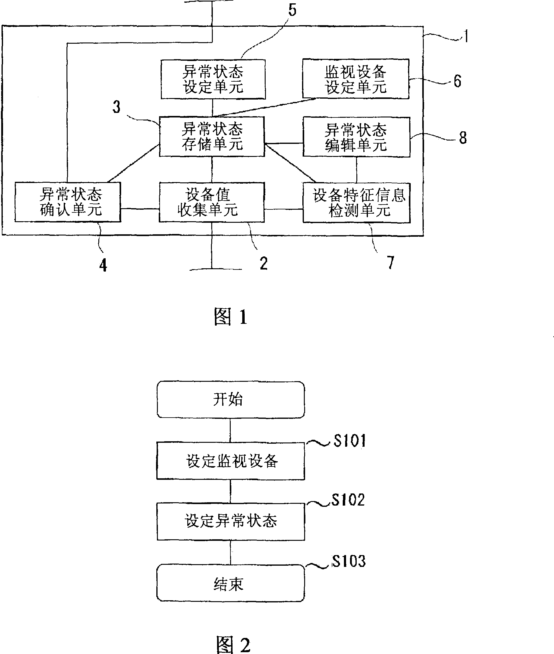
[0029] FIG. 1 is a structural diagram of a data collection device according to Embodiment 1 of the present invention.

[0030] The data collection device 1 in FIG. 1 collects data on equipment values ​​of, for example, a programmable logic controller (hereinafter referred to as PLC) as a monitored device, and monitors the equipment values. Specifically, the data collection device 1 reads and records equipment values, monitors changes in the equipment values, and transmits the abnormality to a management device such as a higher-level computer when an abnormality is detected.

[0031] Describe the structure.

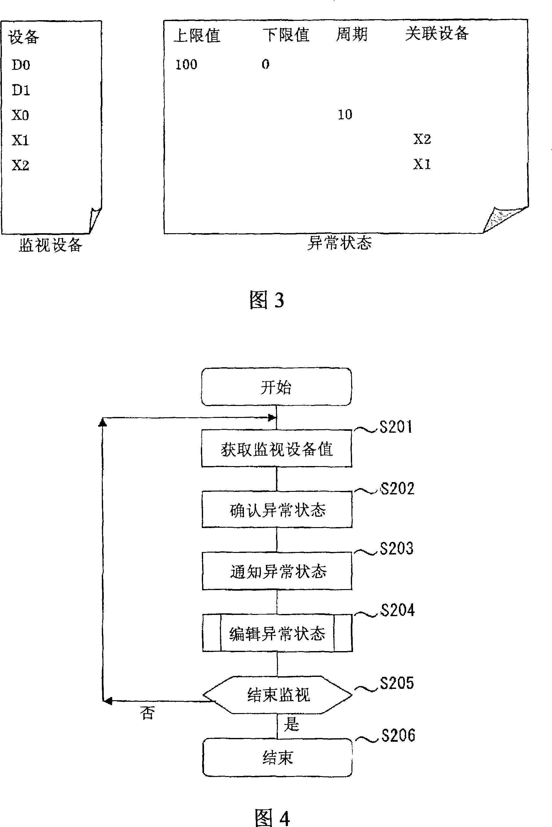
[0032] The data collection device 1 is connected to a control network such as LAN, and the device value collection unit 2 in the data collection device 1 collects device values ​​of PLCs connected to the network.

[0033] The equipment value collection unit 2 is communicably connected with the following units: an abnormal state storage unit 3, which stores thresholds or c...

Embodiment 2

[0060] In Embodiment 1, there is no particular description of the threshold value or condition set by the abnormal state editing unit 8 changing with time, but in Embodiment 2, the threshold value or condition set for the abnormal state editing unit 8 is time Functions are explained. In addition, it is the same as Example 1 unless otherwise indicated.

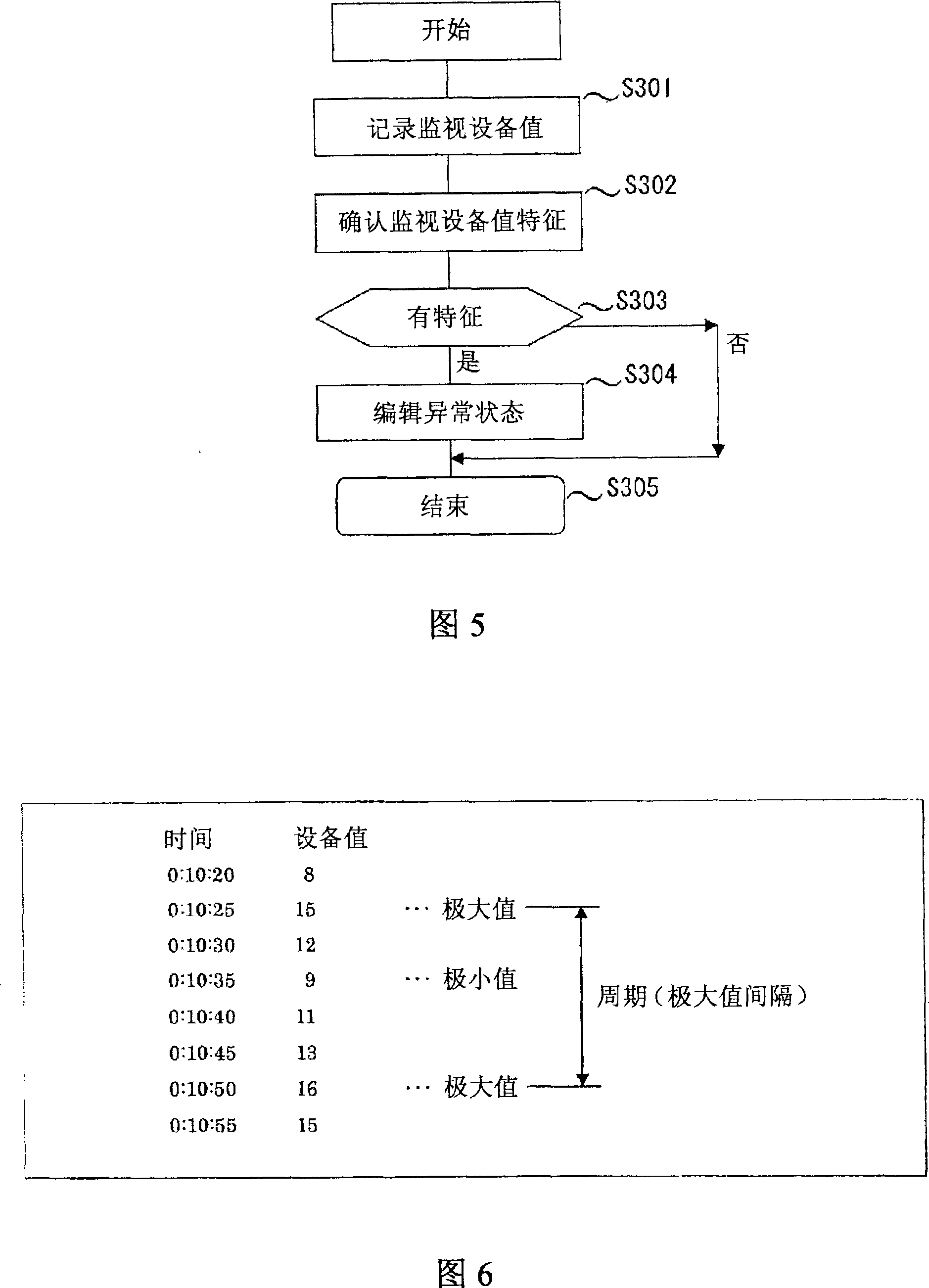
[0061] The PLC or the like to be monitored is the device value of the monitoring device. For example, if the maximum value is not exceeded within a certain period of time, it is predicted that it may be normal that the maximum value is not exceeded. The longer the elapsed time, if it is still normal, it can be presumed that the maximum value will not be greatly exceeded. In other words, an abnormal state can be detected earlier by making the upper limit value gradually approach the maximum value as the threshold value for diagnosing abnormality as time passes.

[0062] Therefore, in order to detect the abnormal state earlier,...

Embodiment 3

[0071] In Example 3, another example of the case where the upper limit value shown in Example 2 is a function of time will be described. In addition, unless otherwise specified, it is the same as in Example 1.

[0072] In the formula (1) of Embodiment 2, since exponential calculation is required, calculation processing time of a computer such as exponential calculation increases. Furthermore, as the data collection device 1 for monitoring PLCs and the like, not only the calculation processing capacity is designed to be the minimum required, but also the collection of device values ​​is given priority, so the calculation processing time is further increased. Therefore, the time required for editing the abnormal state may be increased, and the timing of the next abnormal state monitoring may be delayed.

[0073] Therefore, in the third embodiment, the new upper limit value is set using the expression (2) so that the new upper limit value is a linear function of time t.

[0074...


PUM


Abstract

The invention aims at obtaining a data collection device and a gateway device capable of saving some work required for setting a threshold value and a condition for actual operation, reducing the case of setting an erroneous threshold value or condition, and setting a small range for a threshold value and a condition. The data collection device includes: device value collection means (2) for collecting device values from a plurality of devices; a device-to-be-monitored and abnormal state storage means (3) for storing a threshold value or a condition judging that the device-to-be-monitored has failed; abnormal state check means (4) for comparing device values of devices to the threshold value or condition judging that the device has failed and if so, outputting a corresponding message to a management device of the upper node; device characteristic information detection means (7) for detecting characteristic information from the device values collected by the device value collection means (2); and abnormal state edition means (8) for editing a threshold value or a condition which judges that the device-to-be-monitored has failed and is stored in the abnormal state storage means (3), by using the detected characteristic information.

Description

technical field [0001] The present invention relates to a data collection device and a gateway device, which read and record data from plant equipment, etc. through communication, and simultaneously collect the collected data and detect the data In the event of an abnormality, the abnormality is transmitted to the upper-level server or the like by the communication unit. Background technique [0002] As an example of the prior art, there is a technique described in Japanese Patent Application Laid-Open No. Hei 5-189027 (Patent Document 1). [0003] According to Patent Document 1, there is described a technique for storing the maximum range of signal change or the value of the signal change rate for a fixed time width (sampling period) in the normal operating state of the signal to be diagnosed when diagnosing an abnormality of the signal. The maximum value is taken as the maximum range or maximum rate of change of the signal under normal operating conditions, and the margin...

Claims


Application Information

Patent Timeline
Patent Type & Authority Applications(China)
IPC IPC(8): G05B23/02
CPCG05B23/0262G05B23/0235
Inventor 河野诚一
Owner MITSUBISHI ELECTRIC CORP
Why Eureka
Try Eureka