
High hole dense perforation pressing crack sand controlling device for oil well

A technology with high porosity and pore pressure, applied in wellbore/well components, production fluids, earth-moving drilling, etc., can solve the problems of high oilfield production, small sand control plug volume, and difficulty in large-scale promotion.

Inactive Publication Date: 2008-04-30
营口市石光石油机械有限责任公司
View PDF0 Cites 5 Cited by
  • Summary
  • Abstract
  • Description
  • Claims
  • Application Information

AI Technical Summary

Problems solved by technology

[0004] However, due to the lack of practical experience, there are still some obvious defects in the previous design: first, the density of holes per unit length is low, generally 10 holes / m, which cannot meet the needs of high production in oil fields (general requirements > 13 holes / m )
Secondly, only one hole can be shot on a layer. If the hole capacity is large, the sand control material may not be enough, resulting in a too small volume of the sand control plug, which cannot seal the mouth of the hole, resulting in failure of the sand control operation; if the rock formation is dense and hard, and the hole volume is small, It may cause waste of sand control materials... etc. These shortcomings and defects not only affect the operation effect of the composite perforation-sand control technology, but also bring difficulties to the large-scale promotion of this technology

Method used


Image

  • High hole dense perforation pressing crack sand controlling device for oil well
  • High hole dense perforation pressing crack sand controlling device for oil well
  • High hole dense perforation pressing crack sand controlling device for oil well

Examples


Embodiment Construction

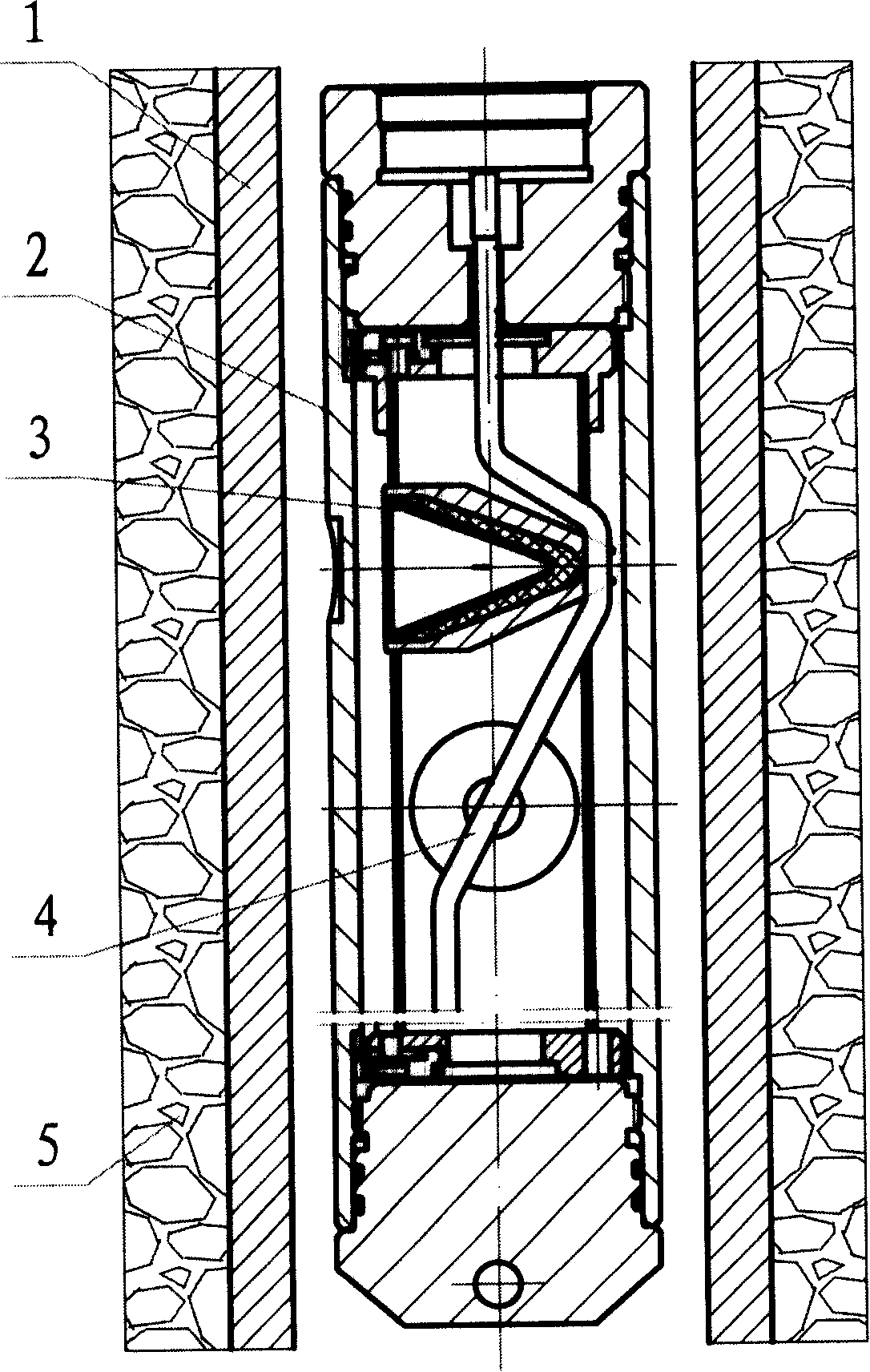
[0017] figure 1 It is a schematic diagram of oil well perforation operation during oil exploration and oil production. During oil production, the casing 1 should be drilled in the oil field, and the space between the casing 1 and the formation 5 should be reinforced with cement, and then the perforating device 3 should be loaded into the perforating gun 2, and inserted into the casing 1 to a proper depth. . When the depth is calibrated, the perforating operation can be performed.

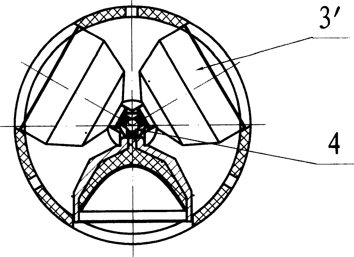
[0018] image 3 The petroleum perforating unit 3' that contains three perforating devices (3) used in the present invention is characterized in that three perforating devices 3 are placed on the position where ordinary perforating devices are usually placed, and the three are placed on their backs. At an angle of 120°, the detonating cord 4 passes through the middle of the detonation holes of the three perforators 3 and connects with the detonation holes.

[0019] Figure 4 For the embodiment (...


PUM


Abstract

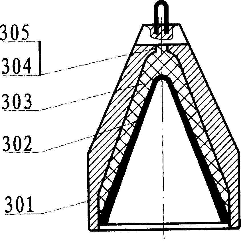
The invention provides an oil well used high-hole dense perforation fracturing and sand controlling device, which includes a perforating unit containing 2-4 perforators and an aftereffect acting part filled with perforated sand preventing material and boosting powder. The invention is characterized in that the perforating unit and the aftereffect acting part are both arranged in a cylindrical boosting chamber, the surface of the boosting chamber is a broken-line or streamline rotating curve, the middle part of the inner cavity are provided with 2-4 round holes for fixing the perforating unit. Fracturing charge is positioned on the outer side of the perforating unit, the sand preventing perforated material is positioned on the two sides of the fracturing charge, and the boosting powder is positioned outside the perforated material. The working principle of the device is using the explosion products of perforator charge to ignite the fracturing charge to fracture oil layer as the perforator perforates; using the high-energy gas produced by the combustion of the boosting powder to push the sand preventing perforated material into and staying in a hole passage punched by liquid jet, and a permanent sand preventing filtering screen is formed in the oil layer. The filtering screen is permeable by oil gas, but can block the quicksand. The invention can enable the perforating, the fracturing and the sand preventing tasks to be completed at once; can improve operation effect of the perforating and sand preventing; and can increase the oil and gas output.

Description

1. Technical field [0001] The invention relates to a well completion device used in an oil field, in particular to a high pore density perforation fracturing sand control device for an oil well. 2. Background technology [0002] During completions in unconsolidated rock formations, sand problems that may arise from well operations must be considered. Fine sand migration in rock formations can be controlled by sand control methods, all of which create a sand barrier. Before formation fluid flows into the wellbore, it must pass through the sand barrier. Sand barriers can be provided mechanically (eg, liners, screens, gravel filters) or by resin injection and plastic consolidation. However, the former has cumbersome process, large investment, short life and high maintenance cost; the latter requires complex "perforation-injection" with complete and superb plastic consolidation technology, and these are very backward in our country. [0003] In the 1990s, people began to stud...

Claims


Application Information

Patent Timeline
IPC IPC(8): E21B43/117E21B43/02
Inventor 史慧生
Owner 营口市石光石油机械有限责任公司
Learn More