Full-wave nonzero dispersion flat single-mode optical fiber

A non-zero dispersion, single-mode optical fiber technology, applied in cladding optical fiber, optical waveguide and light guide, etc.

Inactive Publication Date: 2008-04-30
汪业衡
View PDF0 Cites 10 Cited by
  • Summary
  • Abstract
  • Description
  • Claims
  • Application Information

AI Technical Summary

Problems solved by technology

[0021] In short, there is a considerable gap between the existing single-mode communication fibers and the

Method used


Image

  • Full-wave nonzero dispersion flat single-mode optical fiber

Examples


Embodiment Construction

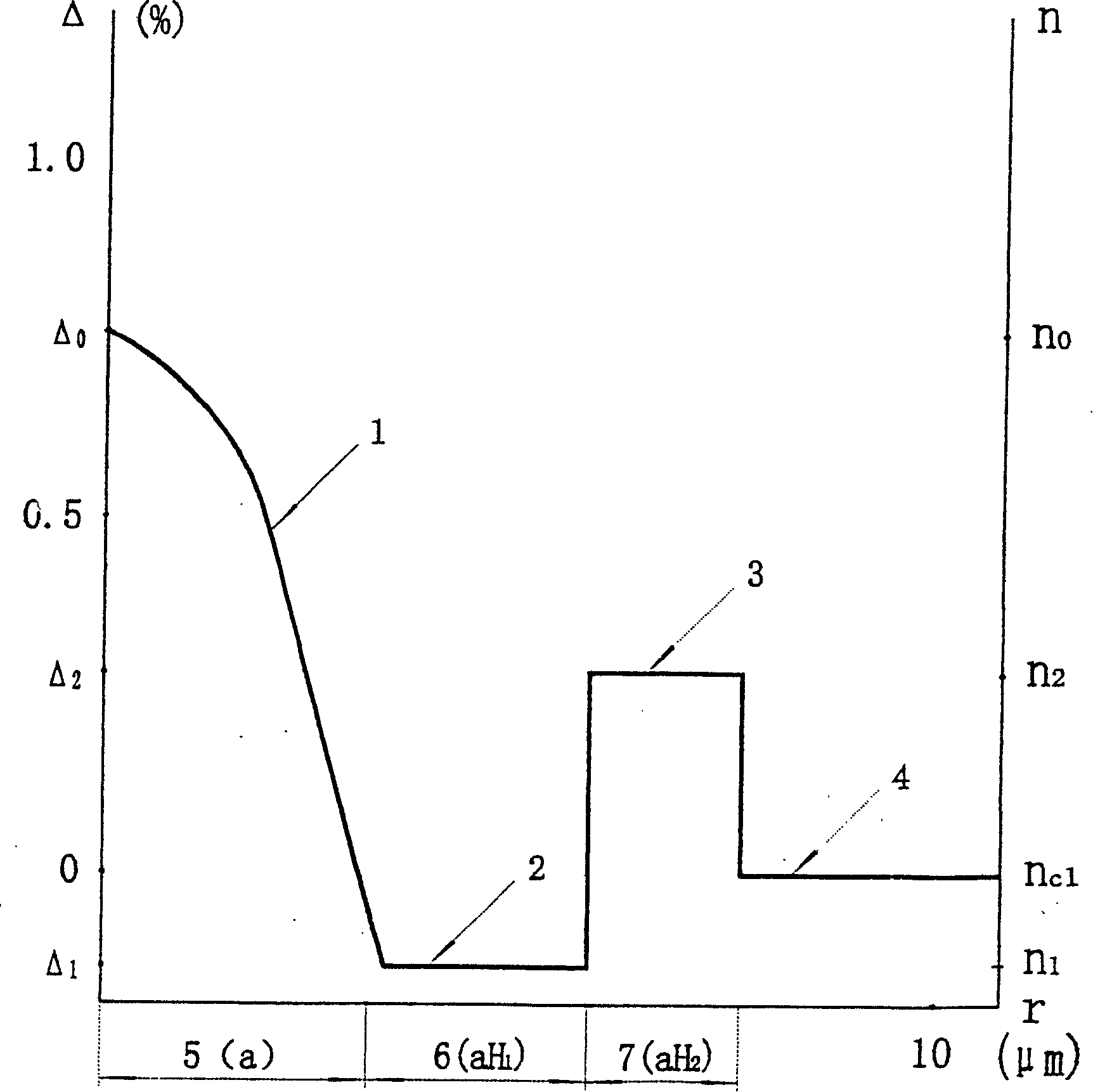
[0032] figure 1 Among them, 1, 2, 3, and 4 represent the central circular layer, the first ring layer, the second ring layer, and the outer cladding of the optical fiber, respectively, and 5, 6, 7 and 8 represent the core center of the fiber. Circular stratification radius a, first annular stratification width H 1 And the second annular layer width H 2 , N 0 Represents the maximum refractive index of the central circular layer of the core, n 1 And n 2 Respectively represent the uniform refractive index of the first annular layer and the second annular layer, n c1 Represents the uniform refractive index of the outer cladding layer. The refractive indices of the first annular layer, the second annular layer and the outer cladding layer are all substantially uniform. The first annular layer Δ 1 2 >0.

[0033] Table 1 shows the main structural parameters of a preferred embodiment of the invented full-wave non-zero dispersion flattened single-mode fiber.

[0034] Table 1

[0035] ...


PUM


Abstract

The invention relates to a complete wave nonzero dispersive flat single mode optical fiber, which comprises a fiber core circular shaped center delamination, a first ring-shaped delamination, a second ring-shaped delamination and a uniform outer cladding. The refractive index of the first ring-shaped delamination is lower than that of the uniform outer cladding. The optimum choose of the refractive index section shape of each delamination, relative refractive index difference and semidiameter or width can guarantee that the chromatic dispersion is between 0.1ps/nm-km and 12.0ps/nm-km in a wavelength range of 1300nm to 1625nm. The valid section Aeff is more than or equel to 50 square micrometers under the condition that the wavelength is 1550nm. The performance of the optical fiber can be changed in different intervals in the range according to the different requirements of communicating systems such as DWDM and CWDM.

Description

Invention field [0001] The invention relates to a full-wave single-mode optical fiber, in particular to a full-wave non-zero dispersion flat single-mode optical fiber. Background technique [0002] The following first gives definitions of the terms involved in the present invention, and the definitions conform to the practice in the field; the specific terms in this specification are explained by conventional terms. [0003] The radius of each layer of the optical fiber is measured in units of μm and defined by the refractive index. Each specific layer has a first refractive index point and a last refractive index point. The radius from the fiber axis to the location of the first refractive index point is the inner radius of the layer; the radius from the fiber axis to the location of the last refractive index point is the outer radius of the layer. Refer to the Δ-fiber radius distribution diagram, the radius of the central circular layer of the core is measured from the fiber ax...

Claims


Application Information

Patent Timeline
IPC IPC(8): G02B6/02
Inventor 汪业衡
Owner 汪业衡
Why Eureka
Try Eureka