Clock synchronization realization method for loop network

A technology of clock synchronization and implementation method, which is applied in the direction of time division multiplexing system, electrical components, multiplexing communication, etc.

Inactive Publication Date: 2008-04-30
NO 3 AUTOMATION INSTR & METERS FACTORY SHANGHAI AUTOMATION INSTR & METERS CO LTD
View PDF0 Cites 31 Cited by
  • Summary
  • Abstract
  • Description
  • Claims
  • Application Information

AI Technical Summary

Problems solved by technology

[0003] The present invention aims at the problem that the device clocks in the existing ring network need to be synchronized, that is, there is a unique clock reference, and proposes a clock synchronization implementation method in the ring network to realize the clock synchronization problem in the ring network

Method used


Image

  • Clock synchronization realization method for loop network

Examples


Embodiment Construction

[0009] Below in conjunction with accompanying drawing and specific implementation method, the present invention is described in further detail:

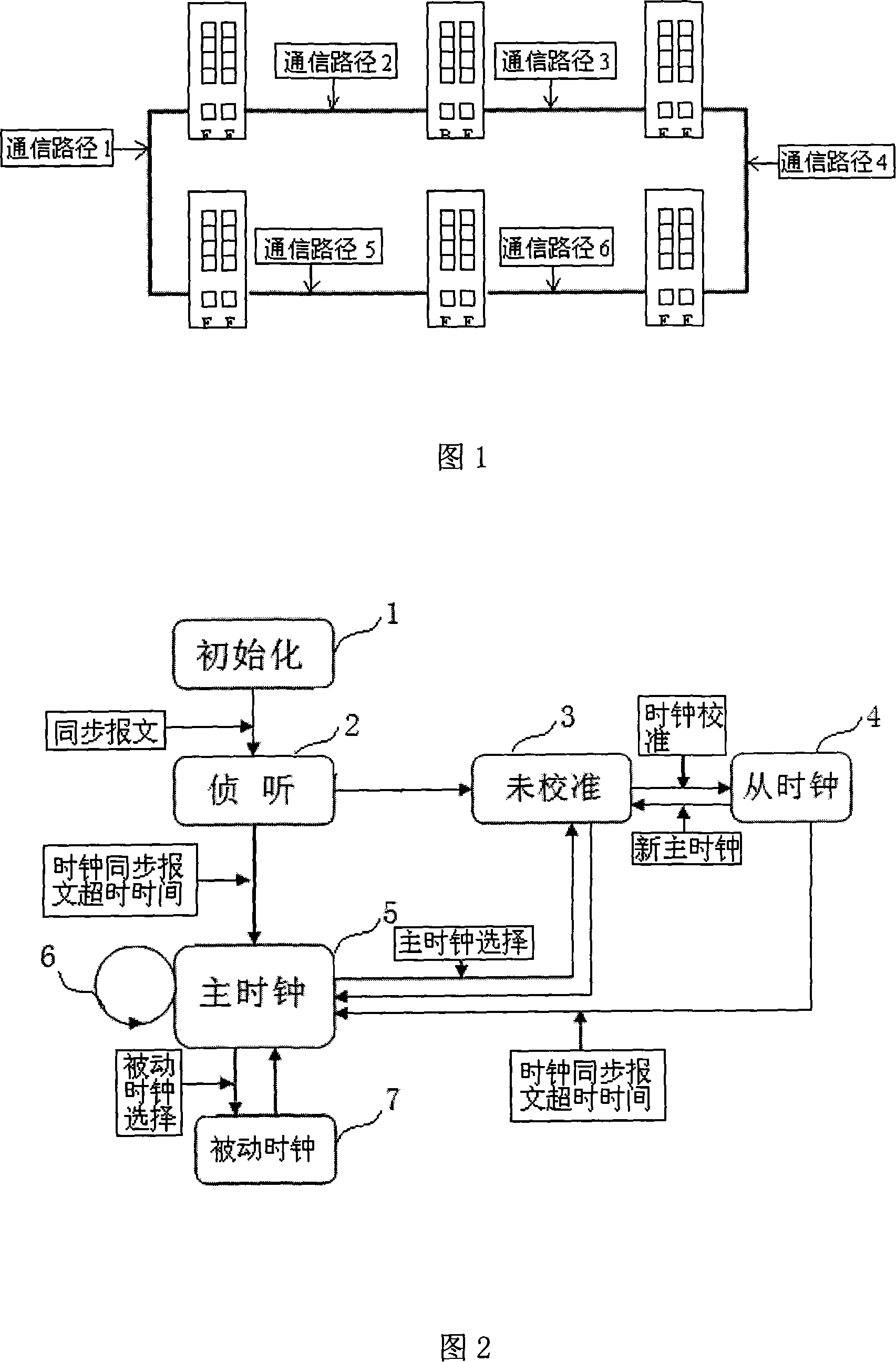
[0010] As shown in Figure 1, the schematic diagram of the topology structure of the ring network, the topology structure of the ring network is given, and the definition of the communication path is given. Since it is stipulated that each device in the network does not forward the received clock-related messages, the adjacent There are independent communication paths between devices.

[0011] As shown in Figure 2, the clock synchronization workflow in the ring network shows the state machine implemented by this method. After the device is powered on, all ports enter the initialization 1 (INITIALIZING) state, which initializes the clock data set of each port. After the device initialization 1 is completed, the PTP port will enter the listening 2 state (LISTENING) and wait for the clock synchronization message. Previously, when receiv...


PUM


Abstract

The invention relates to a method to realize clock synchronization in a ring network. Because what the equipment in the ring network realizes is a boundary clock, the ports thereof can have three status including a master clock, a slave clock and a passive clock, the ports in the status of the master clock are used as a base for the clock on the communication path thereof, and the ports connected therewith needs synchronizing therewith; the ports in the status of the slave clock needs synchronizing with the master clock on the communication path thereof; the ports in the status of the passive clock neglect the clock synchronization information thereon, each port on the communication path thereof conducts master clock competition, and generates three status including the master clock, the slave clock and the passive clock after competition, and therefore, the invention realizes the clock synchronization of equipment under the topological structure of the ring network.

Description

technical field [0001] The invention relates to a method for realizing clock synchronization, in particular to a method for realizing clock synchronization in a ring network composed of industrial Ethernet switches. Background technique [0002] Industrial automation control systems are widely used in electric power, metallurgy, petrochemical and other industries. Communication network technology is the main component of automation control systems. The tasks of connection, configuration, and data exchange of various devices in the control system are inseparable from network and communication. Due to its openness, stability, low cost, high transmission rate, easy networking and many other advantages, Ethernet technology has gradually entered the field of industrial control. More and more automation systems use Ethernet as the communication network. Since the sending and receiving of data packets in the industrial communication network requires deterministic clock information...

Claims


Application Information

Patent Timeline
IPC IPC(8): H04J3/06
Inventor 张庆军包伟华
Owner NO 3 AUTOMATION INSTR & METERS FACTORY SHANGHAI AUTOMATION INSTR & METERS CO LTD
Why Eureka
Try Eureka