Cleaning fixture

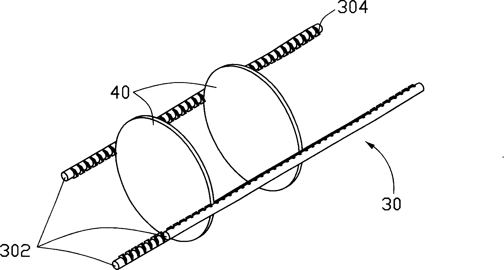
A cleaning fixture and step-shaped technology, which is applied to cleaning methods and tools, manufacturing tools, cleaning flexible objects, etc., can solve the problems that the optical component 40 is difficult to put in, the optical component 40 cannot bear, and is difficult to take out, etc.

Inactive Publication Date: 2008-05-07
HONG FU JIN PRECISION IND (SHENZHEN) CO LTD +1
View PDF0 Cites 7 Cited by
  • Summary
  • Abstract
  • Description
  • Claims
  • Application Information

AI Technical Summary

Problems solved by technology

However, the thickness and depth of the V-groove 304 formed by Teflon will block the water flow, so that the clamped part of the optical component 40 will not be cleaned. Furthermore, during the cleaning process, if the clamped optical component 40

Method used


Image

  • Cleaning fixture
  • Cleaning fixture
  • Cleaning fixture

Examples


Embodiment Construction

[0021] The present invention will be further described in detail below in conjunction with the accompanying drawings.

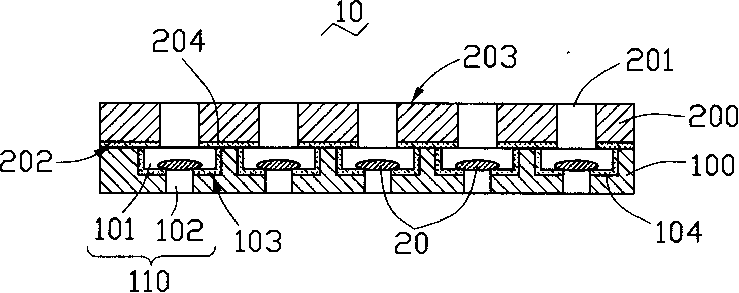
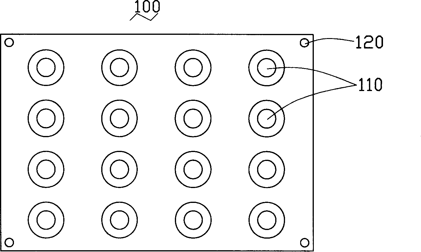
[0022] see figure 2 , the first embodiment of the present invention provides a cleaning jig 10 for cleaning optical components, the cleaning jig 10 includes a carrier plate 100 and a cover 200 .

[0023] There are a plurality of stepped through holes 110 on the carrier plate 100, and the stepped through holes 110 include an accommodating portion 101 and a communicating portion 102, the aperture of the accommodating portion 101 is larger than the aperture of the communicating portion 102, and the A step 103 is formed at the junction of the two. The accommodating portion 101 is used for accommodating the optical assembly 20, and the communicating portion 102 can allow the water flow to contact the optical assembly 20 accommodated in the accommodating portion 101 during the cleaning process of the optical assembly 20, thereby cleaning the optical assembly 20. ...


PUM


Abstract

An apparatus (10) for holding optical lenses (20) provided herein generally includes a holding member (100) and a cover member (200) coupling with the holding member. The holding member comprises a plurality of first through holes (110). Each of the plurality of the first through holes comprises a first portion (101) for receiving an optical lens (20) therein and a second portion (102) communicating with the first portion. A minimum breadth of the first portion is greater than a minimum breadth of the second portion. The cover member comprises a plurality of second through holes (201) corresponding to the first through holes of the holding member. The second through holes communicate with their corresponding first portions of the first through holes. A breadth of the second through holes is less than that of the first portions of the first through holes of the holding member.

Description

technical field [0001] The invention relates to a clamping device, in particular to a cleaning jig for cleaning optical components. Background technique [0002] With the development of multimedia technology, imaging equipment such as cameras, digital cameras, and mobile phone camera lenses are becoming more and more popular among consumers. The image quality puts forward higher requirements, that is, it is hoped that the image of the object to be photographed is clear, and the image quality of the object depends to a large extent on the quality of the optical instruments in the camera. [0003] In-camera imaging modules generally include lenses, optical filters and image sensing components, such as Charge Coupled Device (CCD for short), or Complementary Metal-Oxide Semiconductor (CMOS for short). In the process of producing optical components such as lenses and optical filters, in order to achieve a high degree of cleanliness, these optical components generally need to go ...

Claims


Application Information

Patent Timeline
IPC IPC(8): B08B11/02B25B11/00B08B3/00
CPCG02B27/0006G02B7/02
Inventor 董才士
Owner HONG FU JIN PRECISION IND (SHENZHEN) CO LTD
Why Eureka
Try Eureka