Transmission device

A technology of transmission device and transmission wheel, which is applied in the direction of transmission device, gear transmission device, transportation and packaging, etc. It can solve problems such as the failure of normal operation of the transmission device, the obstruction of glass substrate production and processing procedures, and the peeling of powder chips, etc., and achieves improvement. Unable to deliver normally, increase production competitiveness, improve delivery interruption effect

Inactive Publication Date: 2008-05-14
AU OPTRONICS CORP
View PDF0 Cites 2 Cited by
  • Summary
  • Abstract
  • Description
  • Claims
  • Application Information

AI Technical Summary

Problems solved by technology

[0012] When the first bearing seat 105, the second bearing seat 107 and the positioning plate 103 produce relative movement, friction will be generated between the groove 110 and the protrusion 111 of the positioning plate, so when the glass conveyor table is operated for a long time Finally, the protruding part 111 of the positioning plate is often deformed, or the groove 110 is rubbed for a long time, causing the powder to peel off and blocking the groove 110, which in turn leads to a gap between the protruding part 111 of the positioning plate and the groove 110. The clamping phenomenon makes the first bearing seat 105, the second bearing seat 107 and the positioning plate 103 unable to continue to maintain the normal relative motion, so when the glass substrate 112 is taken away from the roller rings 109, 109' through transmission, the first bearing The seat 105 and the second bearing seat 107 cannot be restored to the initial position when the glass substra

Method used


Image

  • Transmission device
  • Transmission device
  • Transmission device

Examples


Embodiment Construction

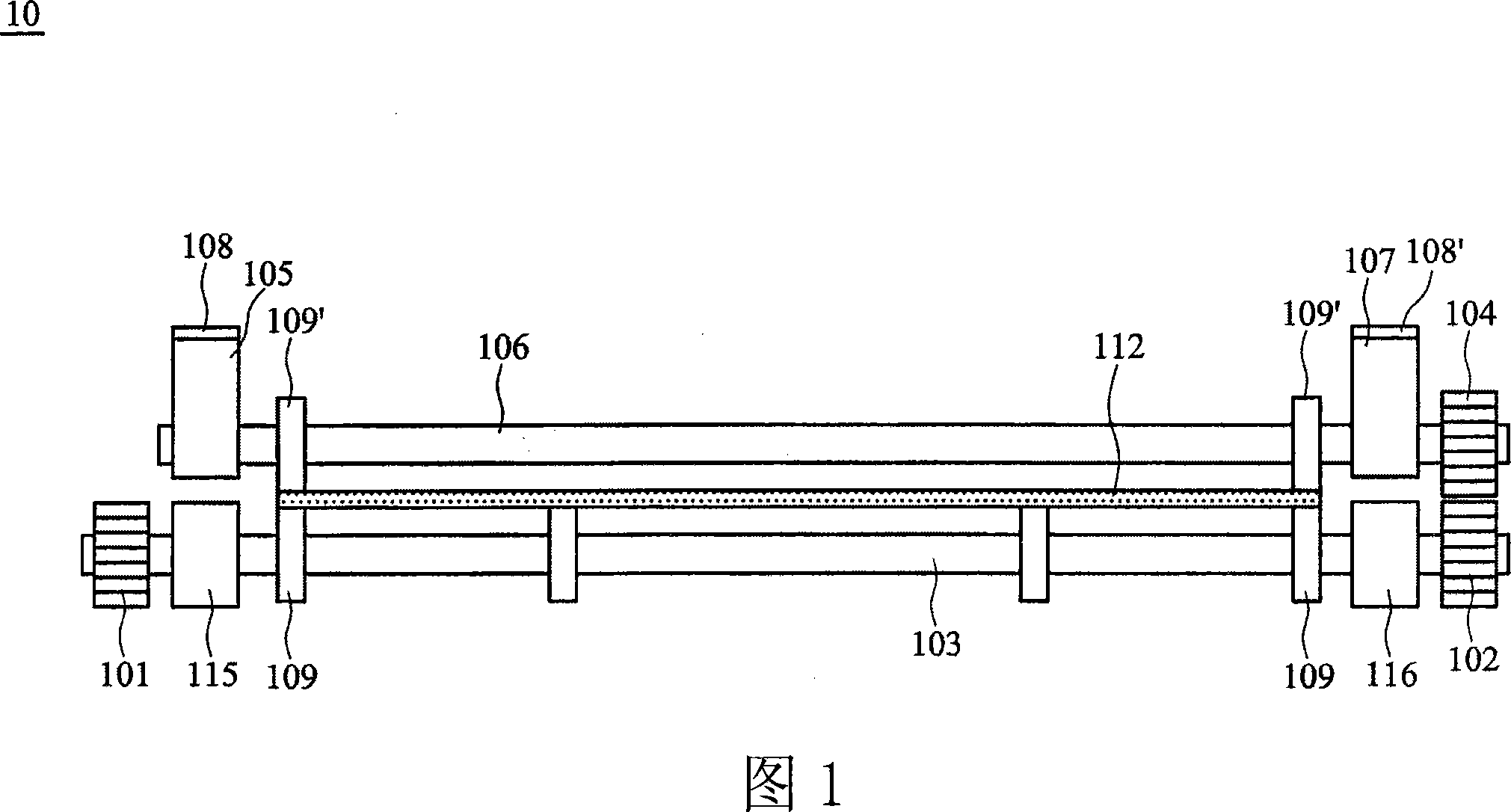
[0080] Fig. 3 shows the schematic diagram of the transmission device embodiment of the present invention, and the transmission device 30 of this embodiment comprises the first transmission wheel 301, the second transmission wheel 302, the lower roller 303, the third transmission wheel 304, the first bearing seat 305, Upper roller 306, first floating assembly 307, second bearing seat 308, second floating assembly 309, first upper cover 310, second upper cover 310', first bearing 321, second bearing 322, and a plurality of rollers Subrings 311, 311'. The link relationship of each component is as follows:

[0081] The lower roller 303 is connected between the first transmission wheel 301 and the second transmission wheel 302, the second transmission wheel 302 is connected (engaged) with the third transmission wheel 304, the upper roller 306 is connected with the third transmission wheel 304, the first Bearing seat 305 is arranged on the top of first bearing 321, and second beari...


PUM


Abstract

The invention discloses a transmission device of conveyor table which is suitable for glass substrate, comprising a first driving wheel, a second driving wheel, a lower roller, a third driving wheel, a first bearing support, an upper roller, a first floating component and a top head. The lower roller is connected between the first driving wheel and the second driving wheel. The third driving wheel is connected with the second driving wheel. The first bearing support is arranged on the first driving wheel. The upper roller is connected between the third driving wheel and the bearing support. The first floating component is arranged on the first bearing support and propped with the first bearing support. The top head is arranged on the top of the first floating component and propped with the first floating component, wherein, the first driving wheel drives the lower roller, simultaneously, drives the upper roller through the second driving wheel and the third driving wheel, and then drives the glass substrate to pass between the upper roller and the lower roller.

Description

technical field [0001] The invention relates to a transmission device suitable for a conveyor platform, in particular to a transmission device for a glass substrate conveyor platform. Background technique [0002] With the rapid advancement of science and technology, the quality of human life has also been improved. Lightweight, thin, low power consumption, high brightness and low-cost liquid crystal displays are loved and accepted by the public, allowing audio-visual users to enjoy a more perfect Visual enjoyment. The glass substrate is one of the main key parts in the liquid crystal display, so the production, processing and delivery procedures of the glass substrate have been paid more attention. [0003] The current glass substrate conveyor generally adopts an L-shaped conveying direction conveyor. The glass substrates stored in the glass storage box are conveyed to the conveyor through a robot arm, and pass through on the conveying base. Etching, washing and air-dryin...

Claims


Application Information

Patent Timeline
IPC IPC(8): B65G49/06B65G13/02F16H1/06
Inventor 袁匡平石佑菘郝心吉
Owner AU OPTRONICS CORP
Why Eureka
Try Eureka