Measurement method of down-hole boring tool (drill) rotative velocity and direction and short node
A technology of rotation speed and measurement method, applied in the direction of drilling measurement, devices using electric/magnetic methods, measurement, etc., can solve non-intuitive and inaccurate problems, and achieve easy implementation, low measurement cost and simple structure Effect
- Summary
- Abstract
- Description
- Claims
- Application Information
AI Technical Summary
Problems solved by technology
Method used
Image
Examples
Embodiment 1
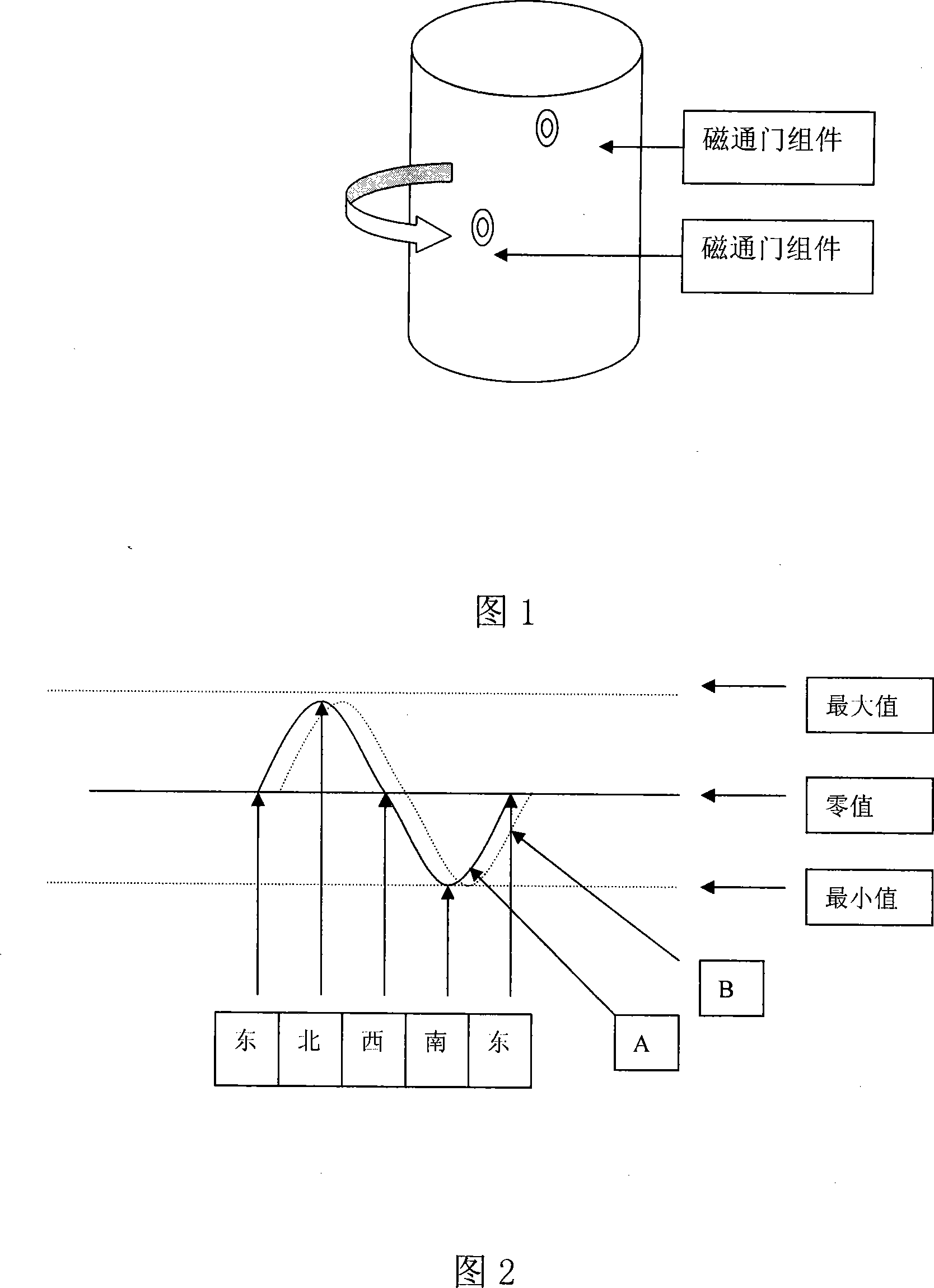
[0029] Embodiment 1, see Fig. 1 and Fig. 2. The magnetic field in nature is distributed according to the north-south direction. Two sets of fluxgate assemblies are installed on the drilling tool (drill bit). Axial vertical lines and located on different horizontal planes. When the drilling tool (drill bit) rotates once, the magnetic field signal measured by the corresponding fluxgate assembly is displayed as a sinusoidal waveform, and a complete waveform represents one rotation. Since two sets of fluxgate assemblies are provided, the magnetic field signals measured by the two sets of fluxgate assemblies are displayed as two sinusoidal waveforms, but their rates are consistent.
[0030] Since the signals sent by the two sets of fluxgate assemblies are displayed as two sinusoidal waveforms, the two sinusoidal waveforms will have a phase difference, and the rotation order of the two sets of fluxgate assemblies can be judged by using the phase difference, and the rotation directi...
Embodiment 2
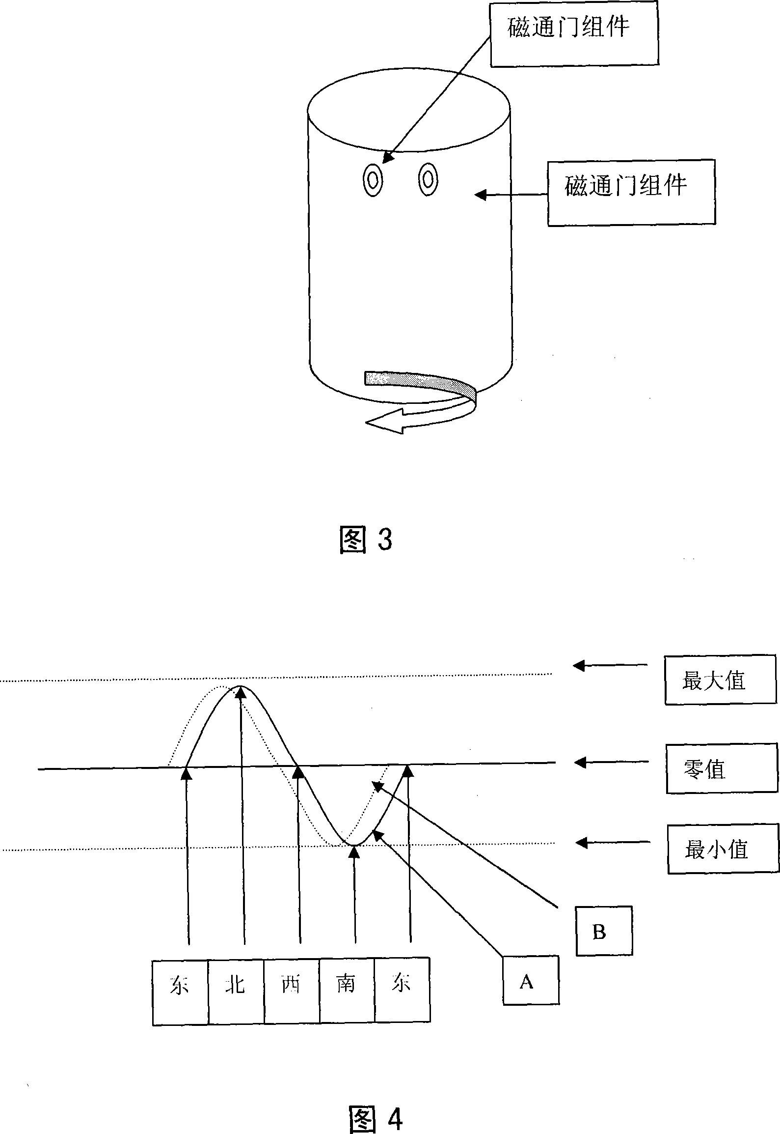
[0031] Embodiment 2, see Fig. 3 and Fig. 4. The magnetic field in nature is distributed according to the north-south direction. Two sets of fluxgate assemblies are installed on a pup joint rigidly connected with the upper part of the drilling tool (drill bit). The two sets of fluxgate assemblies are respectively located at 90 degrees of the pup joint rotation plane Different axial vertical lines in the arc area, and located on a horizontal plane. The speed measurement method is the same as in Example 1.
[0032] Same as Embodiment 1, the rotation sequence of the two sets of fluxgate assemblies can be determined by using the phase difference, and the rotation direction of the drilling tool (drill bit) can also be determined by the rotation direction of the pup joint. In this embodiment, it can be seen that the drill (drill bit) rotates clockwise.
Embodiment 3
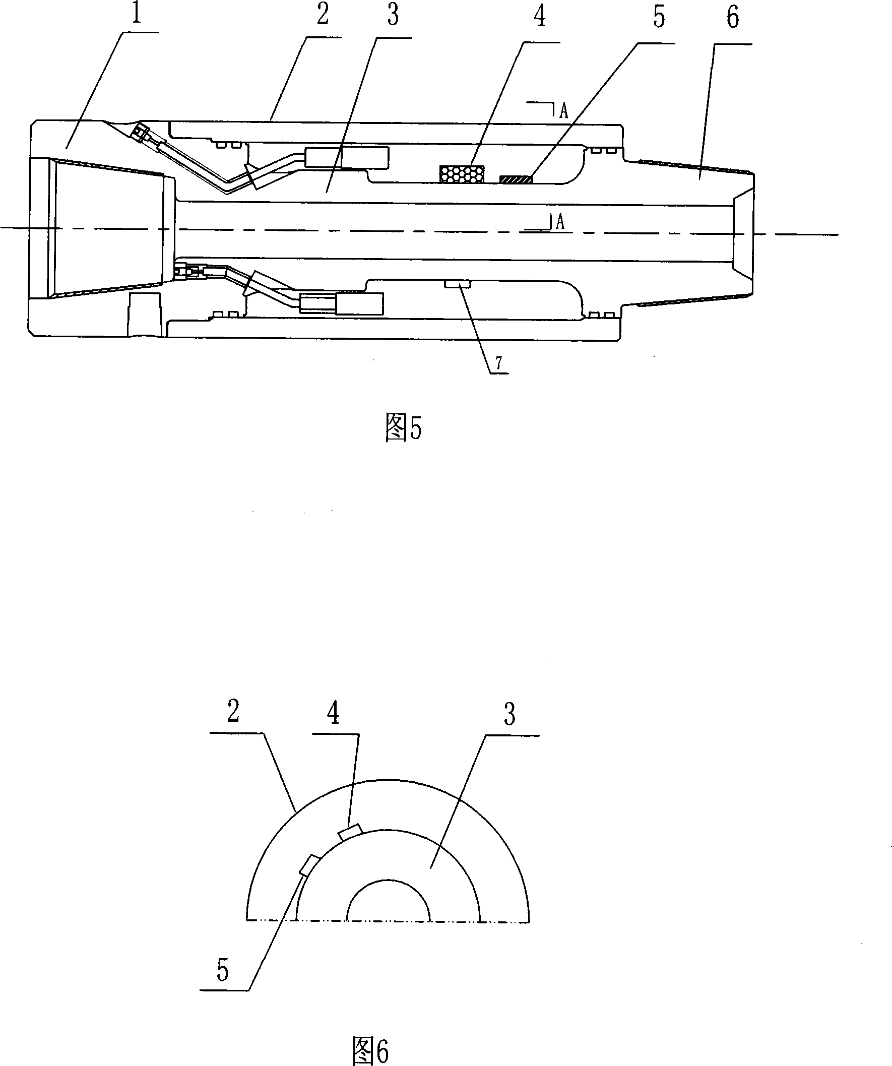
[0033] Embodiment 3, see Fig. 5 and Fig. 6. A short joint for measuring the rotation speed and direction of downhole drilling tools (drill bits, etc.), including a hollow body 3, the two ends of the body 3 are provided with an internal thread connection end 1 and an external thread connection end 6, and the outside of the body 3 is provided with an external thread connection end. The sleeve 2 is provided with two sets of fluxgate assemblies (4) and fluxgate assemblies (5) between the body 3 and the outer sleeve 2 . The two groups of fluxgate assemblies (4) and fluxgate assemblies (5) are respectively located on different axial vertical lines within the 90-degree arc region of the rotating surface, and are located on different horizontal planes. Therefore, the measurement of the rotational speed of the downhole drilling tool is realized by using the fluxgate. Both the fluxgate assembly (4) and the fluxgate assembly (5) include a fluxgate, a control acquisition storage module a...
PUM
 Abstract
Description
Claims
Application Information
 - R&D
- Intellectual Property
- Life Sciences
- Materials
- Tech Scout
- Unparalleled Data Quality
- Higher Quality Content
- 60% Fewer Hallucinations
Browse by: Latest US Patents, China's latest patents, Technical Efficacy Thesaurus, Application Domain, Technology Topic, Popular Technical Reports.
© 2025 PatSnap. All rights reserved.Legal|Privacy policy|Modern Slavery Act Transparency Statement|Sitemap|About US| Contact US: help@patsnap.com


