
Full polarization-preserving fiber interferometer based on 3X3 polarization-preserving fiber coupling mechanism

An optical fiber coupler and polarization-maintaining fiber technology, which is applied in the direction of using optical devices to transmit sensing components, can solve the problems of high control requirements and complex interferometer structure, and achieve the effects of good system stability, simple structure and high sensitivity

Inactive Publication Date: 2008-05-21
BEIJING INSTITUTE OF TECHNOLOGYGY
View PDF1 Cites 9 Cited by
  • Summary
  • Abstract
  • Description
  • Claims
  • Application Information

AI Technical Summary

Problems solved by technology

Polarization-maintaining fiber and 2×2 polarization-maintaining fiber coupler are used to form a full polarization-maintaining Mach-Zehnder interferometer, which solves the problem of system stability, but it uses 2×2 coupler, because the two outputs are in π phase Poor, need to add feedback to lock the working point of the interferometer at the maximum interference sensitivity
This makes the structure of the interferometer more complex and requires higher control

Method used


Image

  • Full polarization-preserving fiber interferometer based on 3X3 polarization-preserving fiber coupling mechanism
  • Full polarization-preserving fiber interferometer based on 3X3 polarization-preserving fiber coupling mechanism

Examples


Embodiment 1

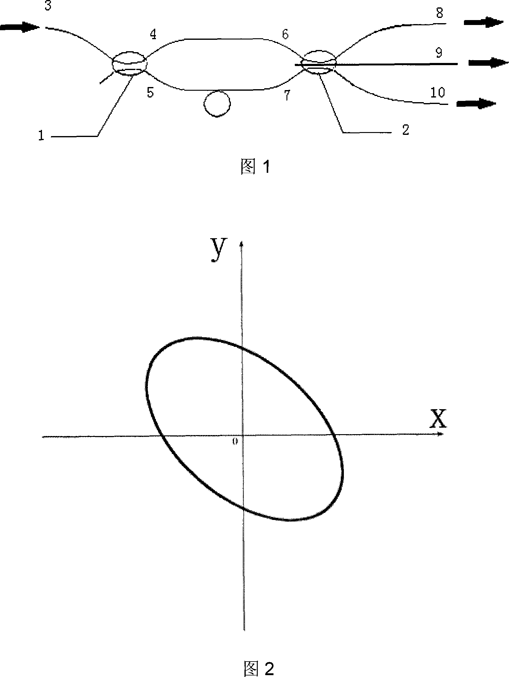
[0017] Fig. 1 is a Mach-Zehnder interferometer formed by using 3×3 polarization-maintaining fiber couplers according to the present invention. Fig. 2 is the Lissajous figure of two signals in the interferometer output of the present invention.

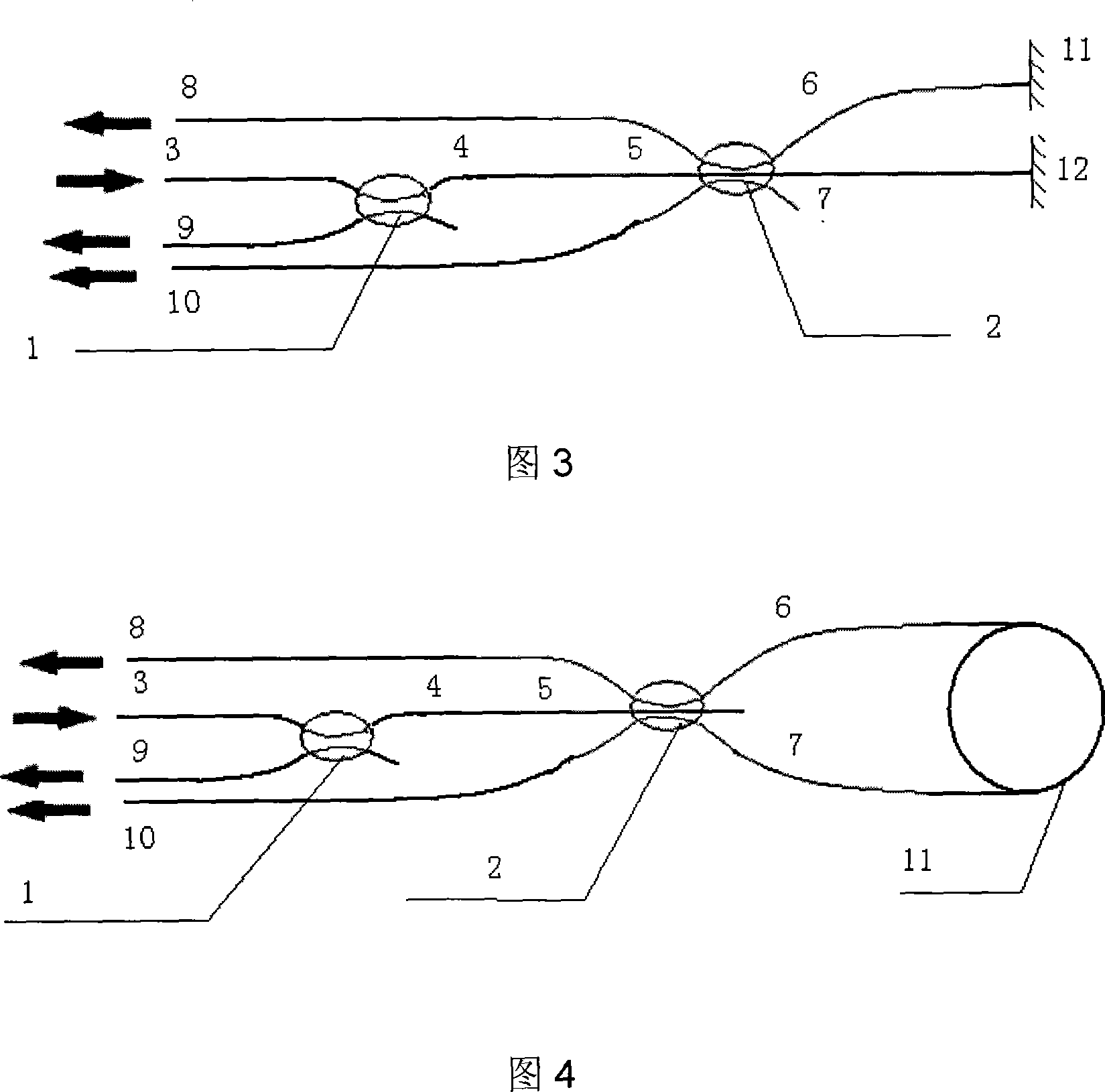
[0018] The Michelson interferometer constituted by the present invention is shown in FIG. 3 . Its structure is that port 3 of 2×2 polarization maintaining fiber coupler 1 is connected with input light source, port 5 of 3×3 polarization maintaining fiber coupler 2 is connected with port 4 of 2×2 polarization maintaining fiber coupler 1, and 3× 3. Port 6 of polarization-maintaining fiber coupler 2 is connected to a signal arm fiber, which is reflected back to port 6 through the end reflector 11. Port 7 of 3×3 polarization-maintaining fiber coupler 2 is connected to a reference arm fiber, which passes through the end reflector 12 reflections return to port 7. Ports 8 and 10 of the 3×3 polarization-maintaining fiber coupler 2 and port 9 o...

Embodiment 2

[0020] The Sagnac interferometer constituted by the present invention is shown in FIG. 4 . Its structure is that port 3 of 2×2 polarization-maintaining fiber coupler 1 is connected to the input light source, and ports 6 and 7 of 3×3 polarization-maintaining fiber coupler 2 are connected to Sagnac ring 11. 3×3 polarization-maintaining fiber coupling Ports 8 and 10 of the optical fiber coupler 2 and port 9 of the 2×2 polarization-maintaining fiber coupler 1 are output terminals of the interferometer, and each output terminal is connected to a detector.


PUM


Abstract

The invention relates to a novel optical fiber interferometer and in particular to an all polarization maintaining optical fiber interferometer consisting of a 3*3 polarization maintaining optical fiber coupler. The invention consists of a 2*2 optical fiber coupler and a 3*3 optical fiber coupler. The 3*3 optical fiber coupler and the 2*2 optical fiber coupler are both the coupler consisting of the polarization maintaining optical fiber. The optical fibers are all polarization maintaining optical fibers and the polarization maintaining optical fiber is parallel to the polarization axis of the coupler; the structure can be Mach-zehnder-type or Michelson-type or Sagnac-type. As the 3*3 polarization maintaining optical fiber coupler is adopted, the interferometer in the structure of the invention has good stability and high sensitivity.

Description

technical field [0001] The present invention relates to a novel optical fiber interferometer, more specifically, the present invention relates to a full polarization maintaining optical fiber interferometer formed by using 3*3 polarization maintaining optical fiber couplers. Background technique [0002] An interferometer is an instrument designed based on the principle of light wave interference. It occupies an important position in optical instruments because of its high sensitivity. The interferometer gives an interference pattern, which reflects the information of the measured object by the change of the interference fringe. The change of the interference fringe can directly measure the length or refractive index, and can also indirectly measure other physical quantities, such as angle, plane Degree, length, airflow density, roughness, surface topography, vibration, speed and acceleration, etc. [0003] Currently commonly used fiber optic interferometers can be divided ...

Claims


Application Information

Patent Timeline
IPC IPC(8): G01D5/26
Inventor 江毅徐晶晶
Owner BEIJING INSTITUTE OF TECHNOLOGYGY
Learn More