Electronic type current mutual inductor

A current transformer, electronic technology, applied in the direction of inductors, instruments, circuits, etc., can solve the problems of poor long-term stability, complex transformer structure, difficult to accurately measure transient fault current, etc., and achieve the effect of high resolution

Inactive Publication Date: 2008-05-21
HUAZHONG UNIV OF SCI & TECH
View PDF4 Cites 28 Cited by
  • Summary
  • Abstract
  • Description
  • Claims
  • Application Information

AI Technical Summary

Problems solved by technology

[0008] The invention provides an electronic current transformer, which uses a Rogowski coil to induce the measured current, and through the cooperation of a VFC circuit, a pulse counter and a microprocessor, integrates and restores the current differential signal output by the Rogowski coil to obtain the measured current. Current signal, to solve the problems of complex structure of current electronic current transformers, difficulty in accurately measuring transient fault current, and poor long-term stability, so as to improve measurement accuracy

Method used


Image

  • Electronic type current mutual inductor
  • Electronic type current mutual inductor
  • Electronic type current mutual inductor

Examples


Embodiment Construction

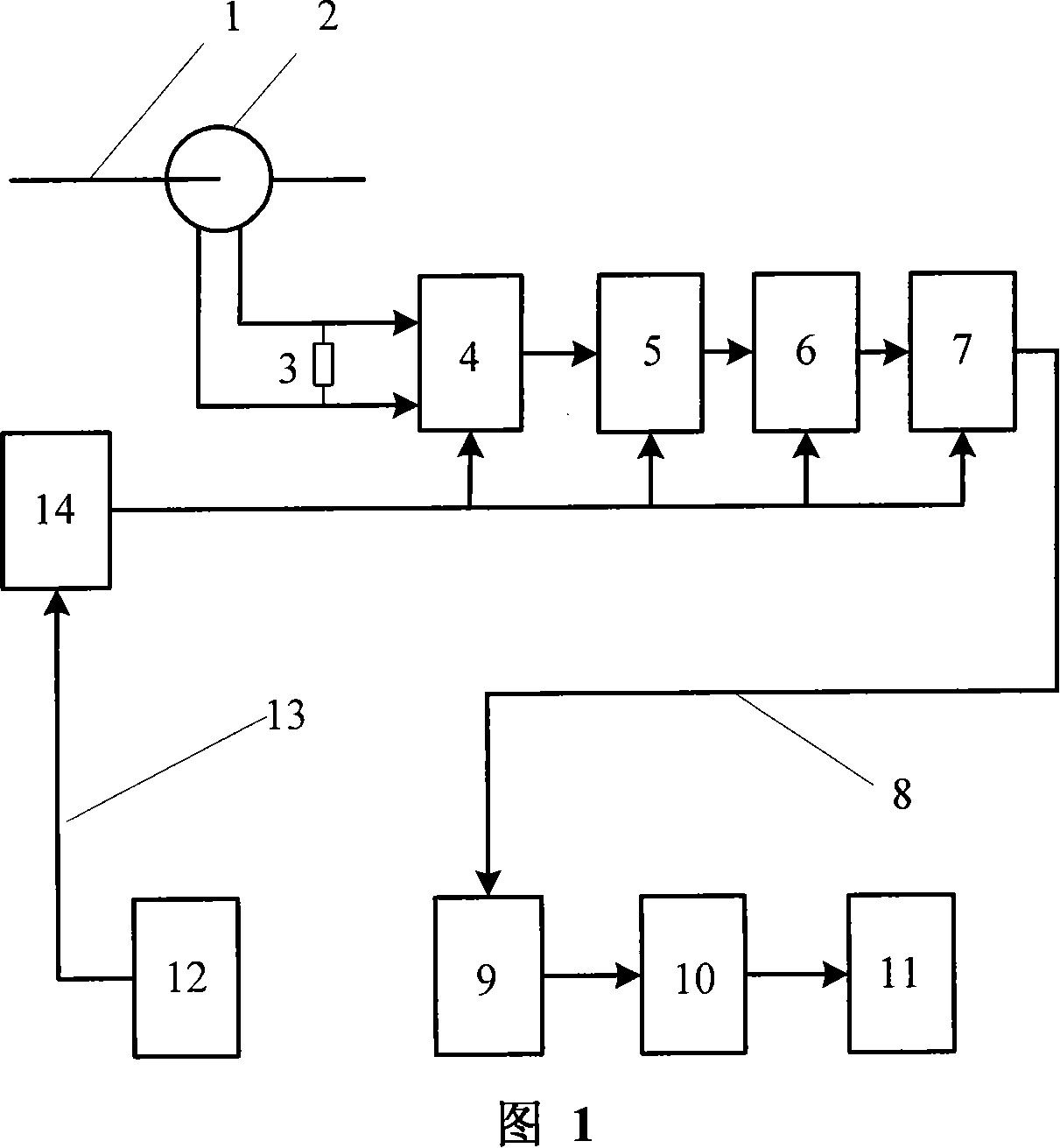
[0060] As shown in Fig. 1, the present invention comprises the sensing unit that is positioned at the high-voltage side, the signal processing unit that is positioned at the low-voltage side and the signal optical fiber 8 that connects both; Resistor 3, low-pass filter circuit 4, amplifier circuit 5, voltage-frequency conversion circuit 6, electro-optical conversion circuit 7; the signal processing unit is composed of photoelectric conversion circuit 9, pulse counter 10 and microprocessor 11.

[0061] The high-voltage side power supply module 14 provides power for the low-pass filter circuit 4, the amplifier circuit 5, the voltage-frequency conversion circuit 6 and the electro-optic conversion circuit 7; the optical energy supply module 12 is connected to the high-voltage side power supply module 14 through the power optical fiber 13 to provide light energy for it .

[0062] The precision operational amplifier OP177 is selected to form the low-pass filter circuit 4 and the amp...


PUM


Abstract

The electronic current transformer belongs to the current transformer of the power system. It is suitable for the current measurement of the high-voltage power system of various voltage levels. It solves the problems of the current electronic current transformer with complex structure, difficult to accurately measure the transient fault current, and poor long-term stability. The high-voltage side sensing unit and the low-voltage side signal processing unit of the present invention are connected by a signal optical fiber, and the sensing unit includes a Rogowski coil, a sampling resistor, a low-pass filter circuit, an amplification circuit, a voltage-frequency conversion circuit, and an electro-optic conversion circuit; the signal processing unit consists of It is composed of photoelectric conversion circuit, pulse counter and microprocessor. The invention has both analog-to-digital conversion function and ideal integrator function. The sensing unit does not need analog or digital integration circuits, and does not need to sample synchronous signals, which greatly simplifies the structure and hardware circuit of the transformer, and improves the reliability of the current transformer.

Description

technical field [0001] The invention belongs to a current transformer of a power system, and in particular relates to an electronic current transformer adopting a Rogowski coil, a voltage-frequency conversion circuit and a pulse counter, which is suitable for current measurement of high-voltage power systems of various voltage levels. Background technique [0002] At present, the power industry mainly uses electromagnetic current transformers with iron cores to measure the primary current. Excessive measured current and non-periodic components in the fault current will easily saturate the core of the electromagnetic current transformer, causing the output waveform of the transformer to be distorted, which may cause the relay protection device to malfunction or refuse to operate. Moreover, most of the electromagnetic transformers used for high voltage are insulated by oil, which has potential safety hazards such as inflammability and explosion. At the same time, with the inc...

Claims


Application Information

Patent Timeline
Patent Type & Authority Applications(China)
IPC IPC(8): H01F38/32G01R15/00
Inventor 尹项根张哲陈德树陈卫李伟
Owner HUAZHONG UNIV OF SCI & TECH
Why Eureka
Try Eureka