Hybrid vehicle drive device

A technology for a hybrid vehicle and a drive device, which is applied in the direction of a hybrid vehicle, a power device, an electric power device, etc., can solve the problems such as the reduction of the performance of the electric motor and the deterioration of the performance of the vehicle.

Inactive Publication Date: 2008-05-21
AISIN AW CO LTD
View PDF1 Cites 19 Cited by
  • Summary
  • Abstract
  • Description
  • Claims
  • Application Information

AI Technical Summary

Problems solved by technology

Therefore, there is a problem that the performance of the motor is lowered or the mounta

Method used


Image

  • Hybrid vehicle drive device
  • Hybrid vehicle drive device
  • Hybrid vehicle drive device

Examples


no. 1 approach

[0028] Next, a first embodiment of the present invention will be described based on the drawings.

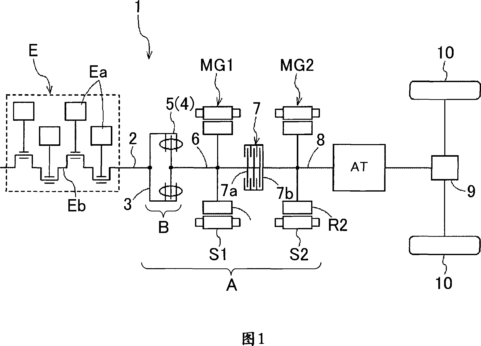
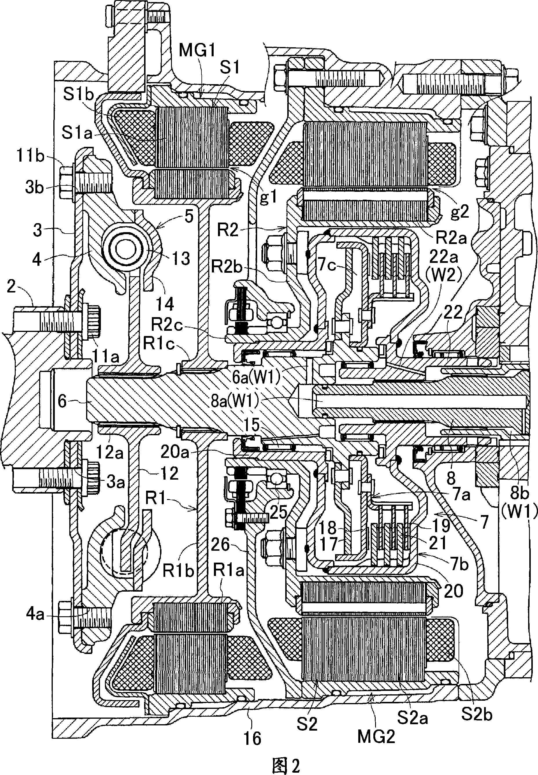
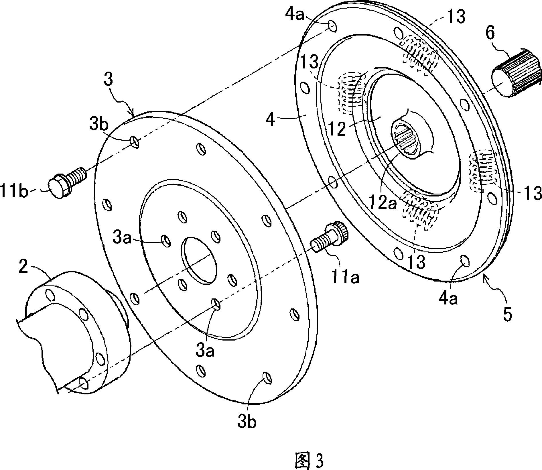
[0029] FIG. 1 is an explanatory diagram showing a schematic configuration of a drive device 1 for a hybrid vehicle according to the present embodiment. FIG. 2 is a cross-sectional view showing a specific configuration of part A in FIG. 1 . Fig. 3 is an exploded perspective view showing a specific configuration of part B in Fig. 1 .

[0030] As shown in FIG. 1 , a drive system 1 for a hybrid vehicle includes two motor / generators MG1 and MG2 between an engine E and an automatic transmission AT. Further, the driving device 1 for a hybrid vehicle, along the transmission path of the driving force from the engine output shaft 2 driven by the engine E, includes the driving disc 3, the damper 5 including the flywheel 4, the intermediate shaft 6, and the first motor. Sequential configuration of / generator MG1, clutch 7, second motor / generator MG2, transmission input shaft 8. The drivi...

no. 2 approach

[0061] Next, a driving device 1 for a hybrid vehicle according to a second embodiment of the present invention will be described. The schematic configuration of the drive device 1 for a hybrid vehicle according to this embodiment is the same as that of the first embodiment described above. FIG. 4 is a cross-sectional view showing a specific configuration of part A in FIG. 1 in the hybrid vehicle drive device 1 according to the present embodiment. As shown in the figure, the driving device 1 for a hybrid vehicle according to this embodiment differs from the above-described first embodiment in that the rotor R1 and the damper of the first motor / generator MG1 are integrally connected by a connecting member 23 . 5. The connecting member 23 is spline-engaged with the intermediate shaft 6 . In terms of other configurations, it can be made the same as that of the above-mentioned first embodiment.

[0062] In the present embodiment, the driven plate 12 of the damper 5 is provided wi...

Embodiment approach

[0066] (1) In each of the above-mentioned embodiments, the following structure has been described, that is, the drive plate 3 as a drive plate is connected to the transmission lower side of the engine output shaft 2, and the reducer equipped with the flywheel 4 is connected to the transmission lower side of the drive plate 3. The composition of vibrator 5. However, the scope of application of the present invention is not limited thereto. For example, the configuration of the transmission disc and the shock absorber 5 can also be exchanged, the shock absorber 5 is connected to the transmission lower side of the engine output shaft 2, and the transmission lower side of the shock absorber 5 is connected to the formation of the transmission disc, which is also One of the preferred embodiments. In such a case, the configuration of the transmission plate itself may be the same as that of the drive plate 3 in the above-mentioned first embodiment. But this time, on the transmission ...


PUM


Abstract

A drive device for a hybrid vehicle, having two electric motors. In the drive device, an air gap between a rotor and a stator of an engine side electric motor can be reduced, and performance enhancement and reduction in size of the electric motors can be achieved. The drive device has a clutch (7) for connecting an engine output shaft (2) and a transmission input shaft (8) when the clutch (7) is engaged, a first electric motor (MG1) capable of transmitting drive force to the transmission input shaft (8) when the clutch is disengaged, and a second electric motor (MG2) capable of transmitting the drive force to the transmission input shaft (8) when the clutch (7) is disengaged. The first electric motor (MG1) is connected to the engine output shaft (2) via a radial vibration suppressing means (3) for suppressing vibration in the radial direction of the engine output shaft (2).

Description

technical field [0001] The present invention relates to a drive device for a hybrid vehicle including two electric motors. Background technique [0002] As a technique related to a drive device for a hybrid vehicle, for example, Patent Document 1 below discloses a drive device for a hybrid vehicle configured as shown in FIG. 5 . The driving device for a hybrid electric vehicle, along the power transmission direction of the engine 101, is composed of the engine 101, the engine output shaft 102, the first electric motor 103, the torsional vibration damper 104, the clutch 105, the second electric motor 106, and the transmission input shaft 107. And the sequential connection of the transmission 108 constitutes. Here, the transmission input shaft 107 is arranged in the axial direction of the engine output shaft 102 . The clutch 105 is arranged coaxially with the rotation center line 109 of the engine output shaft 102 and the transmission input shaft 107, and connects these two ...

Claims


Application Information

Patent Timeline
IPC IPC(8): B60K6/46B60K6/383B60K17/04B60L11/14F16F15/30F16F15/315B60K6/40B60K6/442B60L50/16
CPCF16D25/0638B60W10/06F16F15/123B60K6/405Y02T10/6234B60K6/442B60K1/02B60L15/20B60L2240/421B60L2240/441B60L2240/507B60L2270/145B60L2220/50Y02T10/72B60L50/61B60L50/16Y02T10/62Y02T10/64Y02T10/7072Y02T10/70
Inventor 野村晋一山口康夫山下贡犬塚武
Owner AISIN AW CO LTD
Why Eureka
Try Eureka