Three-phase separator comprising a skimming disc and solid discharge orifices

A separator and peeling disc technology, applied in the field of separators, can solve the problems of small mobility of the separation zone and cannot move the separation zone, and achieve the effect of prolonging the service life

Active Publication Date: 2008-05-28
WESTFALIA SEPARATOR AG
View PDF3 Cites 11 Cited by
  • Summary
  • Abstract
  • Description
  • Claims
  • Application Information

AI Technical Summary

Problems solved by technology

Here, on the one hand, the mobility of the separation zone is still relatively low and it is also not easy to move the separation zone quickly enough during operation over the stri...

Method used


Image

  • Three-phase separator comprising a skimming disc and solid discharge orifices
  • Three-phase separator comprising a skimming disc and solid discharge orifices
  • Three-phase separator comprising a skimming disc and solid discharge orifices

Examples


Embodiment Construction

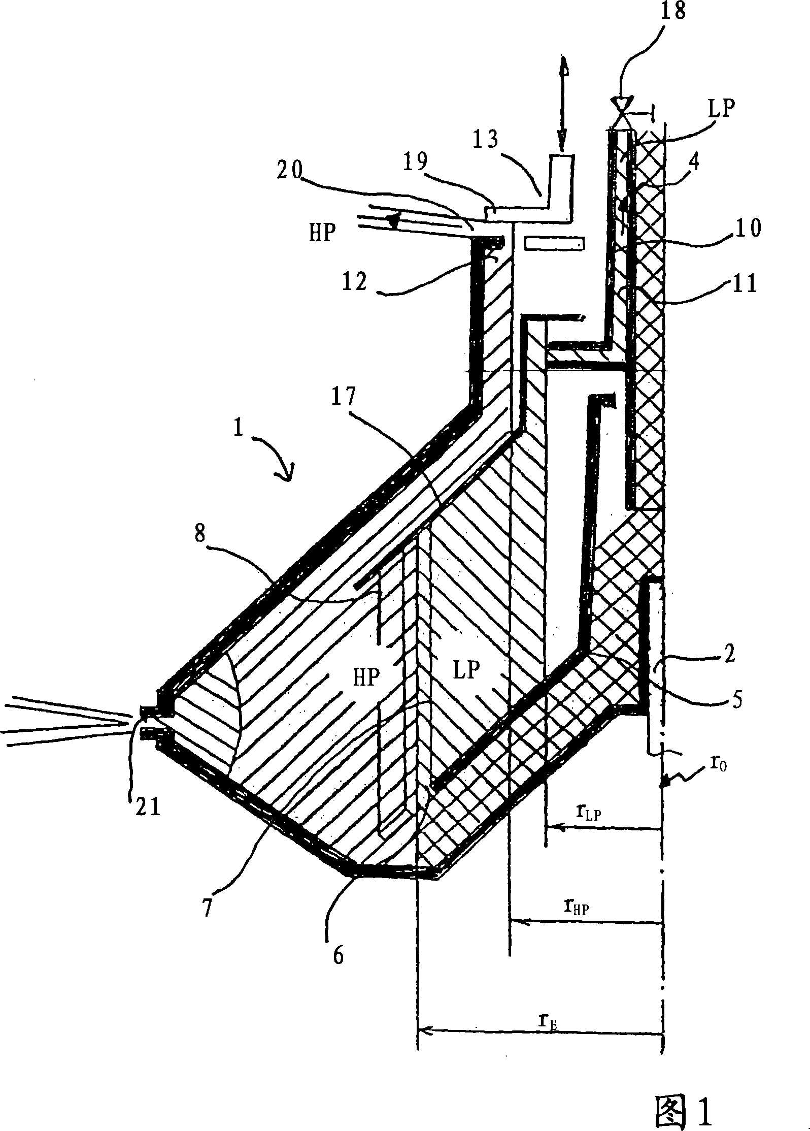
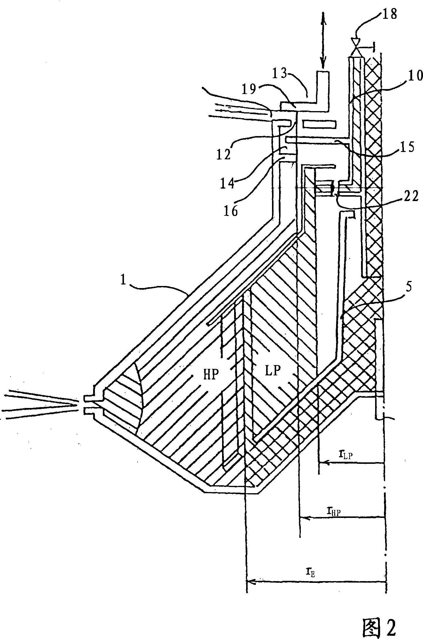
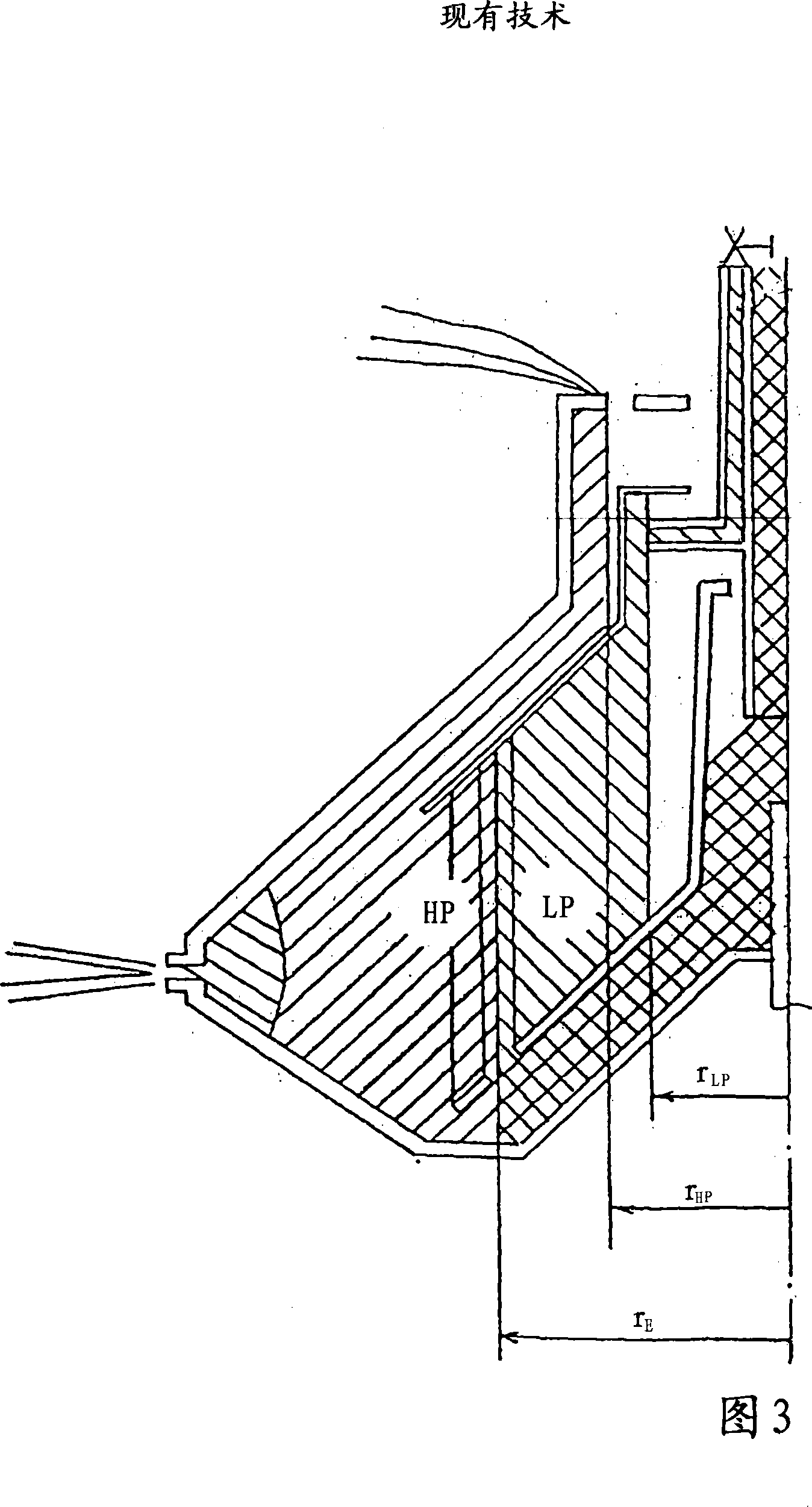
[0026] Figures 1 to 3 show separator drums 1, respectively, which have a radius r 0 has a vertically oriented axis of rotation.

[0027] The separator drums 1 are each mounted on a rotary spindle 2 , which is driven, for example in the form of FIG. 4 , directly or via a belt (not shown here) or in another way (for example, a transmission). The rotary spindle 2 can be formed conically in its upper peripheral region.

[0028] The rotating spindle 2 is pivotally mounted on one side of the drum—here below the drum—by at least one or more roller bearings 3 and thus describes a new centrifuge differently from a screw discharge decanter centrifuge in terms of residual imbalance during operation. axis, which describes an axis around a vertical line r 0 The precession motion (see Figure 4, where the inclination angle α is shown).

[0029] In addition to this type of construction, constructions are also known in which a lower drum is "suspended" as if on the upper rotating shaft. He...


PUM


Abstract

A separator comprising an at least internally single or double-conical separator drum (1) which is mounted rotatably only on one of its axial ends and which has a vertical rotational axis and which also has the following: only at its lower end or at its upper end, a rotary spindle for driving the separator drum, which is mounted so as to oscillate about an articulation point (G), a feed tube (4) for a product to be processed, at least two liquid outlets for a lighter phase (LP) and a heavier phase (HP), wherein the liquid outlet for the lighter phase (LP) is provided with a skimming disc, preferably solid discharge orifices in the region of its greatest internal circumference, a separating pan assembly arranged in the separator drum, wherein an adjustable throttle device (13) is arranged downstream of the liquid outlet of the heavier phase (HP) (12) outside the drum and preferably has an annular disc (19) and is designed to shift the liquid radius R(HP), up to which the heavy phase in the drum extends by changing the exit cross section for the heavy liquid phase - i.e. by partial throttling.

Description

technical field [0001] The invention relates to a separator according to the preamble of claim 1 and to a method for three-phase separation by means of such a separator. Background technique [0002] Such separators have long been known. Usually the liquid outlet is equipped with a so-called peel-off disc, where this effect is used so that the rotational energy of the incoming liquid is converted into a full pressure head in the discharge line. This peeling disc has been tried and tested in practice. In particular, it is possible to vary the resulting total pressure head and thus the separation zone in the drum or the separation zone radius in the drum within a certain range A by throttling. In particular, it is also known to assign peeling discs to the two liquid outlets. [0003] A known three-phase separator is shown in FIG. 3 . If one or both of the two liquid outlets of the drum are provided with a stripping disc and the other outlet is formed nozzle-like, a range A...

Claims


Application Information

Patent Timeline
IPC IPC(8): B04B11/02B04B11/04B04B11/08B04B1/14
CPCB04B1/10B04B11/082B04B11/02B04B1/08B04B2013/006
Inventor K·特雷格H·孔茨
Owner WESTFALIA SEPARATOR AG
Why Eureka
Try Eureka