Compressor
A technology for compressors and casings, applied in the field of compressors, can solve the problems of reduced sealing performance, reduced crimping strength, and reverse installation of the front and back, so as to ensure the sealing performance and improve reliability.
- Summary
- Abstract
- Description
- Claims
- Application Information
AI Technical Summary
Problems solved by technology
Method used
Image
Examples
Embodiment 1
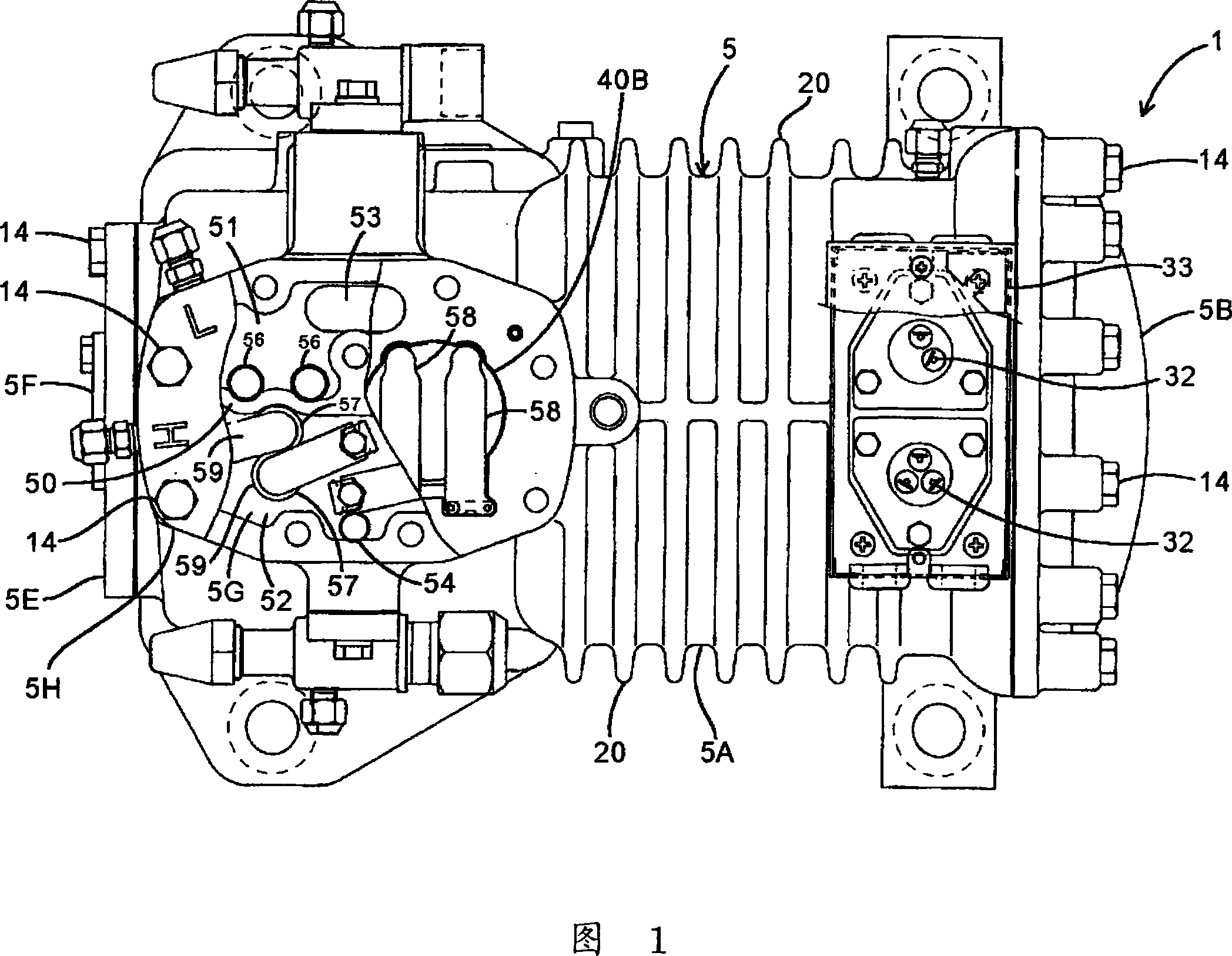
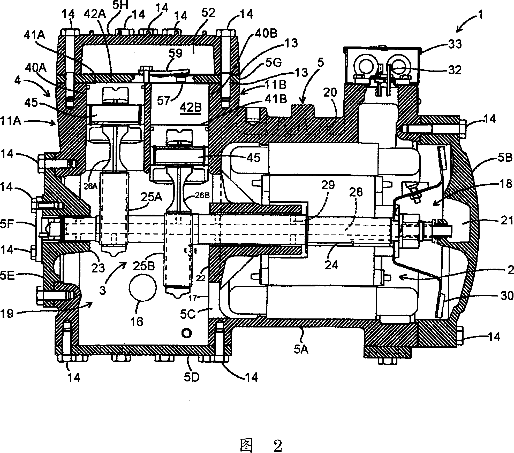
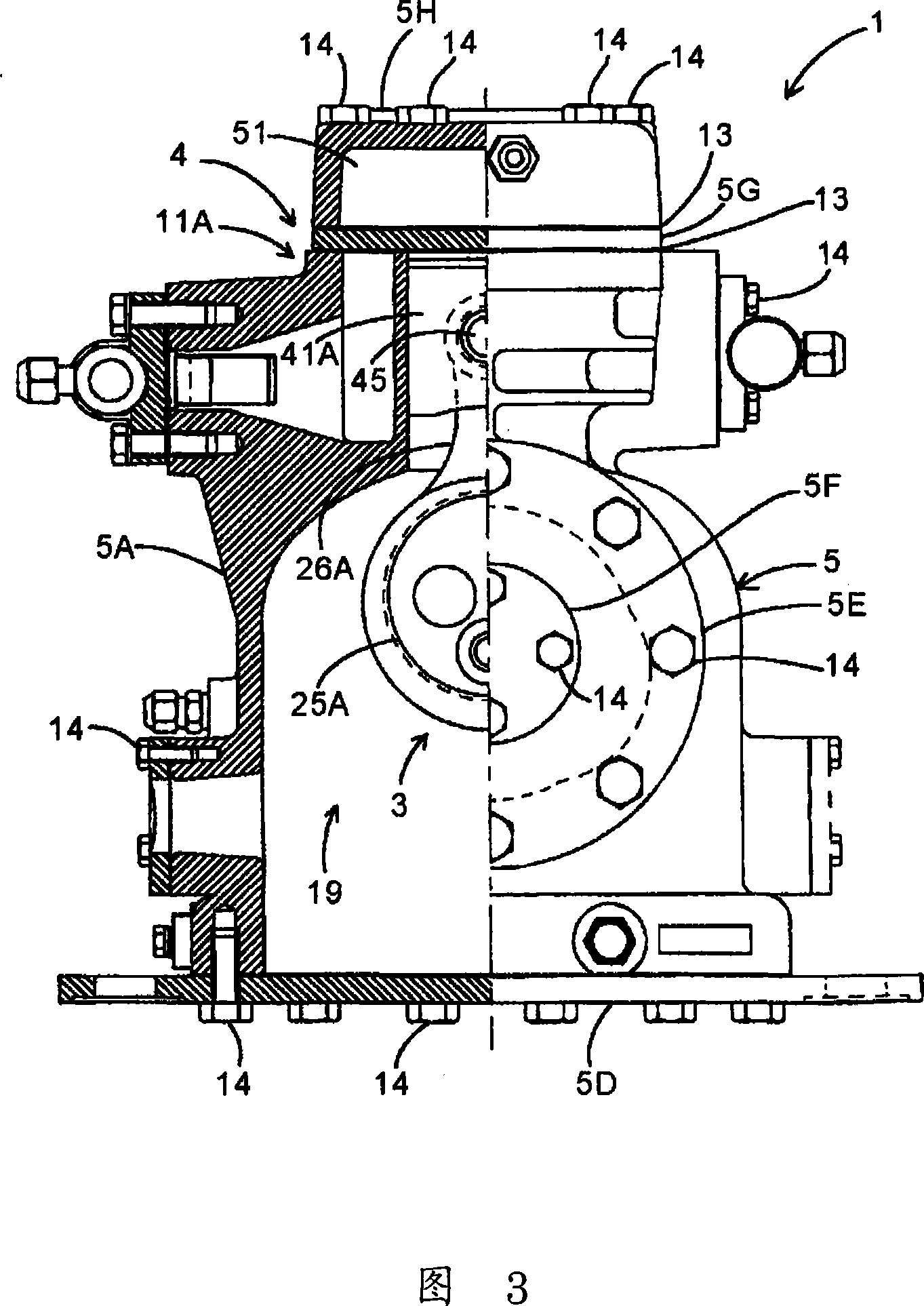
[0040] Fig. 1 is a top view of a semi-hermetic compressor 1 applicable to an embodiment of the present invention, Fig. 2 is a longitudinal section front view of the compressor 1, Fig. 3 is a partial longitudinal section side view of the compressor 1, Fig. 4 is a compressor 1 is an exploded longitudinal sectional front view, FIG. 5 is an exploded partial longitudinal sectional side view of the compressor 1, FIG. 6 is a top view of the first metal gasket 13A installed on the compressor 1, and FIG. The top view of the second metal spacer 13B.
[0041]The compressor 1 of the embodiment is composed of a motor (drive element) 2 that generates rotational power, a power conversion member 3, a compression member 4, and a housing 5 that accommodates them. The power conversion member 3 converts the rotational power generated by the motor 2 to The compression part 4 is driven by the reciprocating power converted by the power conversion part 3 to compress the refrigerant (for example, natu...
Embodiment 2
[0082] In addition, even when the position of one positioning pin 65 is changed as in the above-mentioned embodiment, the positioning hole 68 is not limited to be arranged continuously with the outer rib 61B. For example, as shown in FIGS. 12 and 13, the positioning hole is arranged at The inner side of the outer rib 61B makes the two positioning holes formed on the metal spacers 13A, 13B to be in different positions when the front and the back are turned over, so that the present invention is also effective. In addition, in FIG. 12 and FIG. 13 , members assigned the same reference numerals as those in FIGS. 1 to 11 mentioned above are members having the same or similar effect or function, and description thereof will be omitted here.
[0083] The positioning hole 69 formed on the first metal washer 13A of the present embodiment is located inside the outer rib 61B, that is, it is not continuous with the rib 61B. Therefore, it is not necessary to form reinforcement around the po...
Embodiment 3
[0086] Next, another embodiment of the sealing member (the first metal gasket 13A and the second metal gasket 13B) interposed between the valve plate 5G and the casing main body 5A of the compressor 1 will be described with reference to FIGS. 14 and 15. illustrate. In this embodiment, the position of one positioning pin 65 passing through the positioning hole 67 is kept unchanged from the past, and the position of the other positioning pin 65 is changed so that the positioning hole formed on the first gasket 13A is located on the outer side of the reinforcement. The outer side of rib 61B. In addition, the compressor 1 used in this embodiment has the same structure as that of Embodiment 1 described in FIGS. 1 to 5 , FIG. 8 , and FIG. . In addition, in FIG. 14 and FIG. 15 , members assigned the same reference numerals as those in FIGS. 1 to 13 mentioned above are members having the same or similar effects or functions, and descriptions thereof are omitted here.
[0087] The p...
PUM
 Abstract
Description
Claims
Application Information
 - R&D
- Intellectual Property
- Life Sciences
- Materials
- Tech Scout
- Unparalleled Data Quality
- Higher Quality Content
- 60% Fewer Hallucinations
Browse by: Latest US Patents, China's latest patents, Technical Efficacy Thesaurus, Application Domain, Technology Topic, Popular Technical Reports.
© 2025 PatSnap. All rights reserved.Legal|Privacy policy|Modern Slavery Act Transparency Statement|Sitemap|About US| Contact US: help@patsnap.com


