Modularized equipment hot-plugging module powering method and hot-plug control circuit

A control circuit, hot-swap technology, applied in electrical program control, emergency protection circuit devices, program control in sequence/logic controllers, etc., can solve problems such as large inrush current, reduce power waste, and improve the overall Reliability, the effect of improving the impact of inrush current on the system

Inactive Publication Date: 2008-06-04
RUIJIE NETWORKS CO LTD
View PDF0 Cites 20 Cited by
  • Summary
  • Abstract
  • Description
  • Claims
  • Application Information

AI Technical Summary

Problems solved by technology

[0007] The main purpose of the present invention is to provide a hot-swappable control circuit to realize hierarchical power-on of multiple electrical equipment of the hot-swappable module, and effectively solve the problem of excessive inrush current when the modules of the modularized equipment are hot-swapped , so as to solve the problem that the power supply of the modular equipment needs to be reserved more, and improve the reliability of the modular equipment

Method used


Image

  • Modularized equipment hot-plugging module powering method and hot-plug control circuit
  • Modularized equipment hot-plugging module powering method and hot-plug control circuit

Examples


Embodiment 1

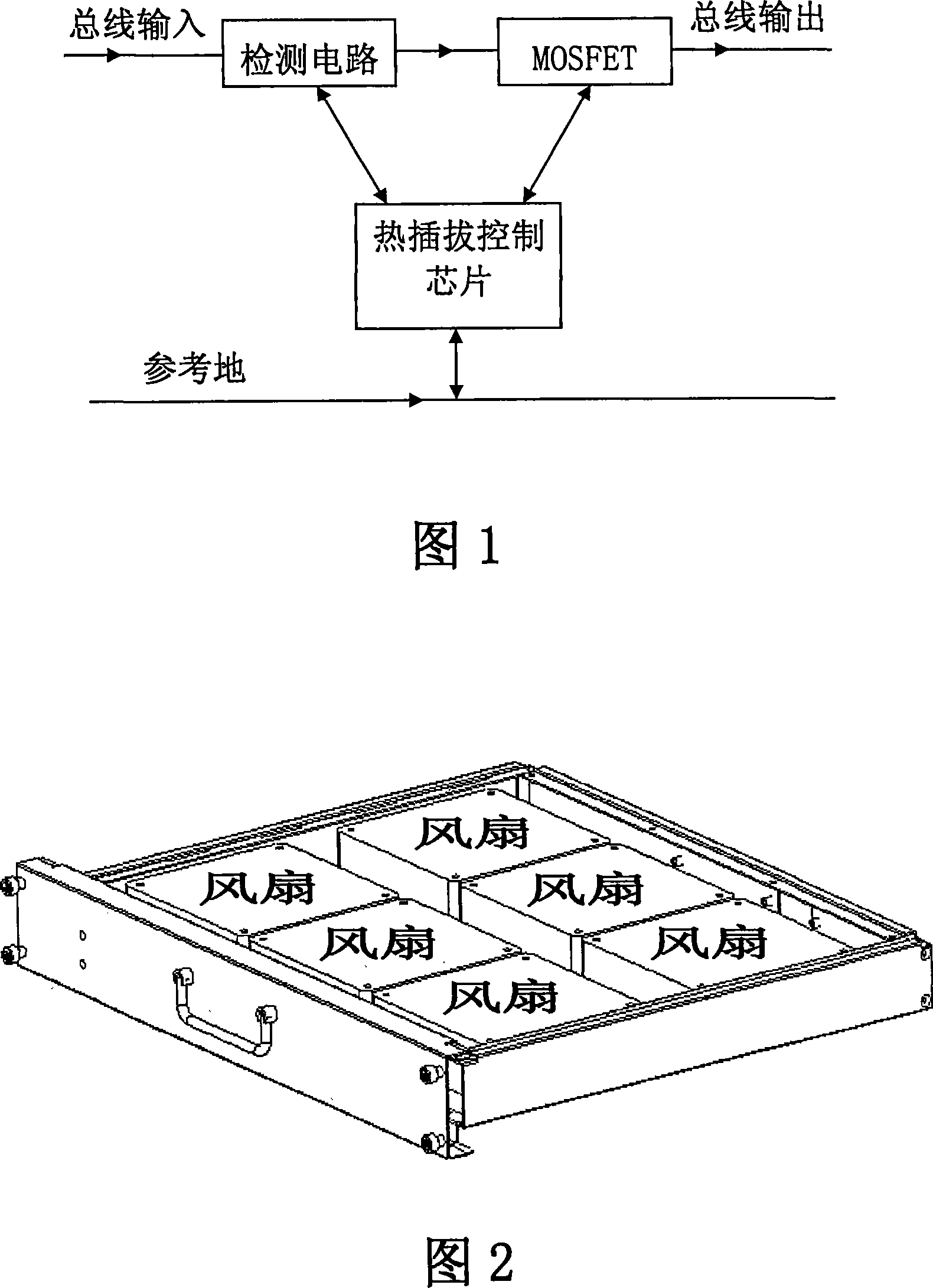
[0035] This embodiment provides a hot swap control circuit. In order to achieve the purpose of hierarchical power-on, the present invention improves the hot-swap control circuit of the module system of the modular equipment, and improves the control circuit that controls power-on by one hot-swap control chip to be controlled by multiple hot-swap control chips A control circuit that controls power-on. FIG. 3 is a schematic diagram of the hot swap control circuit when the fan modules of the modular switch are powered on in three stages according to this embodiment. As shown in Figure 3, the hot-swap control circuit includes: a three-stage hot-swap control unit, which is used to respectively control the three groups of fans of the hot-swap fan module to be powered on; and two delay circuits, the first delay The timing circuit is set between the first-level hot-swap control unit and the second-level hot-swap control unit, and is used to drive the second-level hot-swap control uni...

Embodiment 2

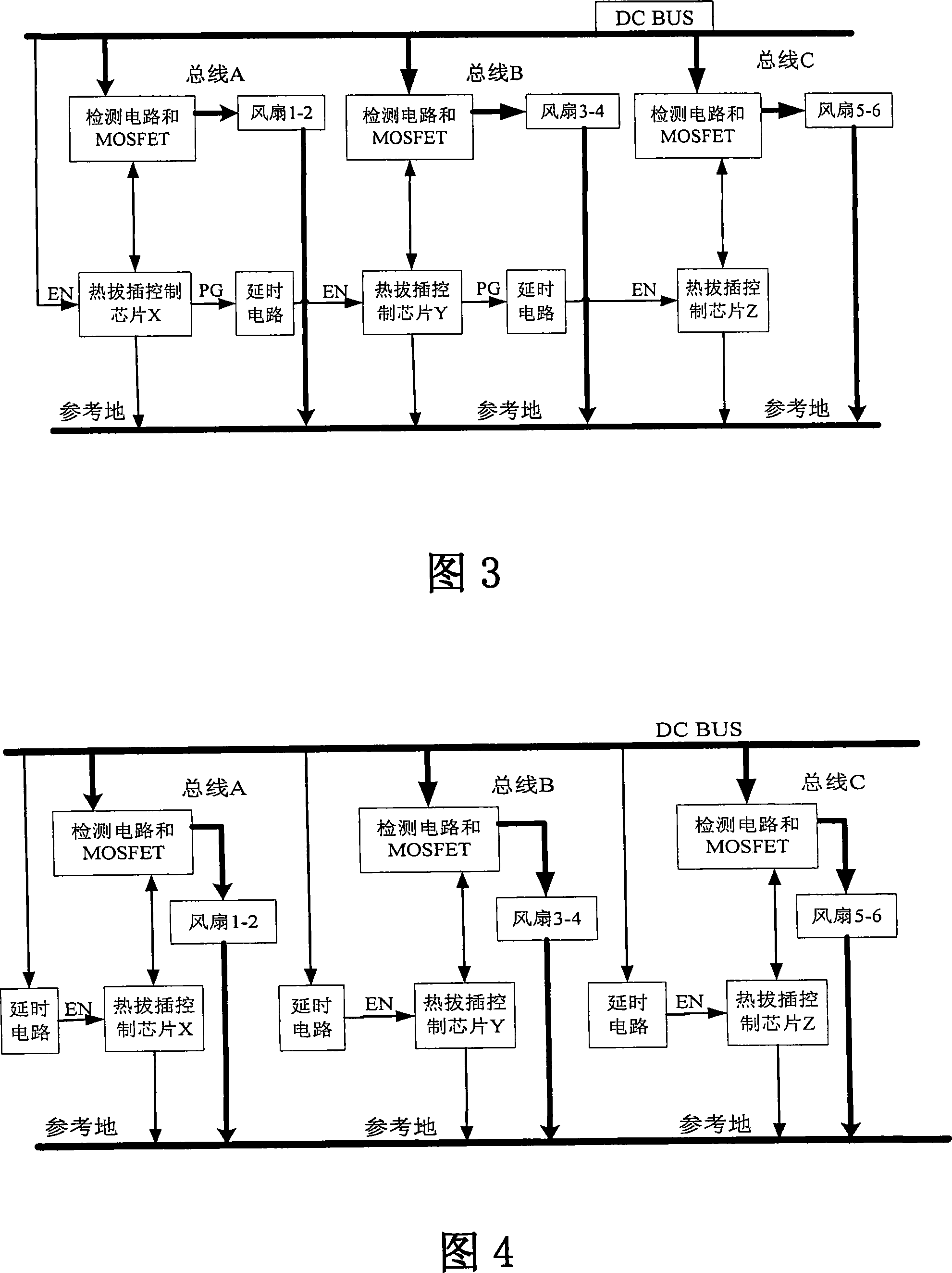
[0041] This embodiment further provides a hot swap control circuit. FIG. 4 is a schematic diagram of the hot swap control circuit when the fans of the fan module are powered on in three stages according to this embodiment. As shown in Figure 4, the hot-swap control circuit includes: a three-stage hot-swap control unit, which is used to control multiple groups of electrical equipment of the hot-swap module in parallel to power on; and three delay circuits, respectively connected The hot-swap control units at all levels are used to drive the hot-swap control units at all levels, and through different delays of the delay circuit, multiple groups of electrical equipment of the hot-swap module are powered on at different times. The delay circuit described in this embodiment is typically an RC circuit. If an accurate delay is desired, a classic delay circuit such as NE555 can be considered.

[0042] In this embodiment, the hot-swap control unit at each stage includes: a detection c...

Embodiment 3

[0047] This embodiment provides a hierarchical power-on method for hot-swappable modules in a modular device, and the method includes the following steps:

[0048] In the grouping step, the electrical equipment (such as fans) of the hot-swappable module is divided into multiple groups, and each group of electrical equipment is hung on different parts of the power supply bus (as shown in bus A, B, and C in Figure 3 and Figure 4) , or in other words, divide the bus of the modular device into several power-consuming parts. It is not very sensitive to delays in powering up between sections of the powered bus or between groups of powered devices.

[0049] In the staged power-on step, the corresponding multiple hot-swappable control units are used to control the multiple groups of electric equipment to be powered on at different times.

[0050] Taking a fan module with 6 fans as an example, the step-by-step power-on steps for implementing power-on in three stages include:

[0051]...


PUM


Abstract

The present invention provides an electrifying method of thermal inserting-pulling modules in modular devices, as well as a thermal inserting-pulling control circuit. The thermal inserting-pulling control circuit comprises a multilevel thermal inserting-pulling control unit which is used for respectively controlling a plurality of groups of electrical devices of a thermal inserting-pulling module for electrifying, as well as at least one delay circuit which is used to control the electrifying time of at least one thermal inserting-pulling control unit to the electrical devices, so as to electrify a plurality of groups of electrical devices at different time. The embodiment of the present invention realizes the graded electrifying of a plurality of electrical devices of the thermal inserting-pulling module, effectively solves the problem that the impact current is overgreat when the modules of modular devices are thermally inserted or pulled, and reduces the power waste of whole machine power supply of modular devices.

Description

technical field [0001] The invention relates to the technical field of hot swapping, in particular to a power-on method and a hot swapping control circuit of a hot swapping module in a modular device. Background technique [0002] Hot swapping refers to replacing faulty parts or adding new parts when the modular equipment is turned on and running normally. The hot-swap function allows users to take out and replace damaged fans, power supplies or boards and other components without shutting down the system or cutting off the power supply, thereby improving the system's ability to recover from disasters in a timely manner, scalability and flexibility, etc., for example Some modular devices for high-end applications (such as modular switch systems) can provide hot-swappable functions such as fan modules and power modules. The modularization of the modularized equipment refers to the standardization of interfaces and sizes of components with different performances but with cert...

Claims


Application Information

Patent Timeline
Patent Type & Authority Applications(China)
IPC IPC(8): G05B19/04H03K17/08H02H11/00
Inventor 李泽春陈林峰
Owner RUIJIE NETWORKS CO LTD
Why Eureka
Try Eureka