A communication method between upper device and lower device
A lower computer and a lower computer technology, applied in the field of communication, can solve problems such as low efficiency, achieve the effect of improving operating efficiency and simplifying the complexity of command processing
Inactive Publication Date: 2010-08-18
ZTE CORP
View PDF0 Cites 0 Cited by
- Summary
- Abstract
- Description
- Claims
- Application Information
AI Technical Summary
Problems solved by technology
Method used
View moreImage
Smart ImageViewing Examples
Examples
Embodiment Construction
Login to View More PUM
 Abstract
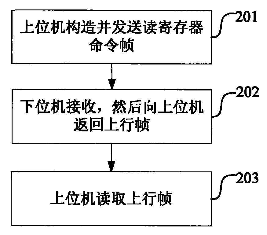
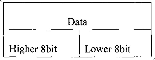
The invention discloses a communication method between a host computer and a lower computer. The host computer communicates with the lower computer by sending a downlink frame and receiving an uplink frame;wherein, the downlink frame comprises a write register command frame and a read register command frame and the host computer realizes the control over the lower computer by sending the write register command frame or the read register command frame; the register addressing mode is used for the downlink frame or the uplink frame and a frame structure with a fixed frame length is used for thedownlink frame or the uplink frame. The adoption of the method of the invention converts any control functions initiated by the host computer into a read command or a write command on the host computer and the lower computer only needs to accomplish two simple operations of writing and reading the register and returning the result, thus simplifying the command processing complexity of the lower computer, greatly enhancing the operation efficiency of the processor of the lower computer and ensuring that the host computer can efficiently control the lower computer and real-timely acquire the operation state information of the lower computer.
Description
technical field The invention relates to the communication field, in particular to a communication method between an upper computer and a lower computer. Background technique In the development of embedded systems, it is a very common method for the upper computer to realize the control of the lower computer through asynchronous serial communication. The upper computer is the initiator of the command, and the lower computer is the executor of the command. However, under normal circumstances, the upper computer does not consider the difficulty of implementing a certain control command for the lower computer, and it is inappropriate if some commands have too much computation for the lower computer. The processor of the lower computer should complete its application functions as much as possible, and the implementation of command analysis and communication protocol processing should be as simple and unified as possible. However, the current communication method between the u...
Claims
Login to View More Application Information
Patent Timeline
 Patent Type & Authority Patents(China)
IPC IPC(8): H04L29/06H04L12/12
Inventor 吴安军
Owner ZTE CORP
Features
- R&D
- Intellectual Property
- Life Sciences
- Materials
- Tech Scout
- Unparalleled Data Quality
- Higher Quality Content
- 60% Fewer Hallucinations
Learn More Browse by: Latest US Patents, China's latest patents, Technical Efficacy Thesaurus, Application Domain, Technology Topic, Popular Technical Reports.
© 2025 PatSnap. All rights reserved.Legal|Privacy policy|Modern Slavery Act Transparency Statement|Sitemap|About US| Contact US: help@patsnap.com


