Electronic entity with magnetic antenna

An electronic entity and antenna technology, applied in the field of electronic entities, can solve the problems of too thick, complex electronic entity design structure, crowding and so on

Inactive Publication Date: 2008-06-04
OBERTHUR CARD SYST
View PDF2 Cites 7 Cited by
  • Summary
  • Abstract
  • Description
  • Claims
  • Application Information

AI Technical Summary

Problems solved by technology

[0005] However, increasing the number of turns quickly leads to some problems: on the one hand, increasing the area carrying these turns relative to the available area can cause crowding problems, especially when the turn geometry is relatively fixed, which is the case when electronic entities have This is especially troublesome in the case of small form factors; on the other hand, the few areas that can usually be used to accommodate these turns (for example, often deposited in the same plane) must use bridging techniques to loop the circuit, as in as disclosed in patent application FR 2 769 390
[0006] Some techniques have been proposed to simplify the design or fabrication of the bridge, for example by combining looping and connection with the electronic circuit, but again the need to loop the magnetic antenna is still required, and this instead makes the proposed electronic entity design more structured. is complex or too thick

Method used


Image

  • Electronic entity with magnetic antenna
  • Electronic entity with magnetic antenna
  • Electronic entity with magnetic antenna

Examples


Embodiment Construction

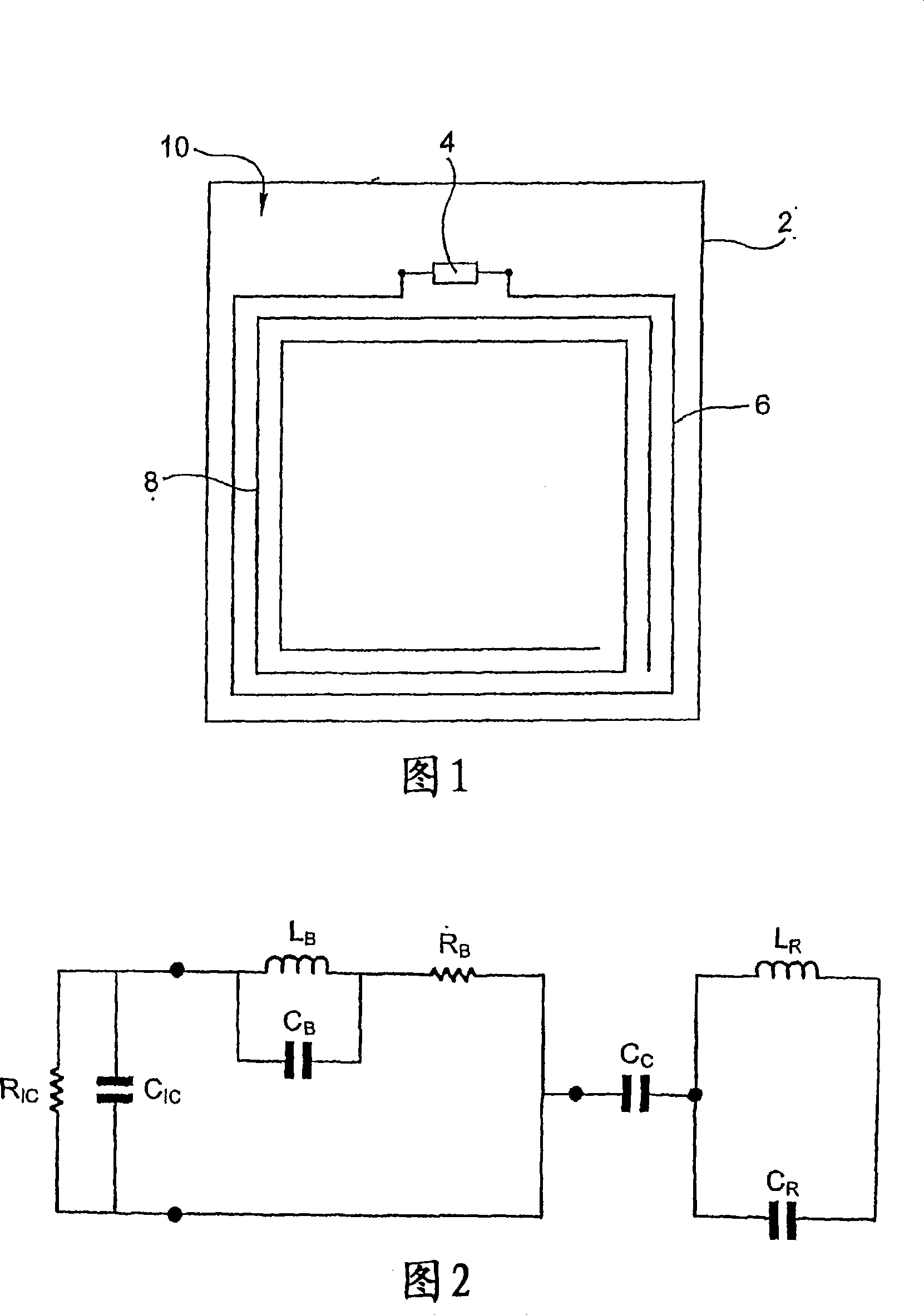
[0049] Figure 1 shows a first example of an electronic entity formed according to the invention. Here it is a microcircuit card 2 on which are shown the components essential to the understanding of the invention, namely the electronic circuit 4 (such as an integrated circuit) and the electronic circuit 4 The antenna formed by the loop 6 and the resonator 8 is connected to the terminal of .

[0050] For example, the electronic circuit 4 is integrated into a module just deposited on the electronic entity 2 in order to connect the electronic circuit 4 to the antenna (here actually the loop 6 ), as disclosed in document FR 2 863 747, for example.

[0051] The antenna enables the electronic circuit 4 to communicate with other electronic devices such as card readers at a distance. This antenna is a magnetic antenna, not only for information exchange at a predetermined frequency between the electronic circuit 4 and external electronic equipment, but also for remote power supply to t...


PUM


Abstract

The invention concerns an electronic entity comprising an electronic circuit and an antenna one part of which at least forms a conductive circuit connected to two ends of the electronic circuit. The projection of the circuit formed by the antenna and the electronic circuit in a plane which is substantially parallel thereto, forms an intersection-free line and the antenna includes a winding which extends over strictly more than one turn.

Description

technical field [0001] The invention relates to electronic entities with magnetic antennas. Background technique [0002] Such an electronic entity generally comprises an electronic circuit having in particular two terminals to which are connected a magnetic antenna, usually formed by winding several turns of conductive material. [0003] Such electronic entities cover in particular contactless microcircuit cards (where a magnetic antenna constitutes the only means of communication between the microcircuit and the outside world) and so-called "dual" or "hybrid" microcircuit cards (here one surface of the card is provided with a realization Another mode of electrical contact for a microcircuit to communicate with the outside world). In whatever microcircuit card, the turns of the magnetic antenna typically appear as coils of copper wire or conductive tracks, in both cases arranged within those layers that physically constitute the card. [0004] In all cases, in order to in...

Claims


Application Information

Patent Timeline
Patent Type & Authority Applications(China)
IPC IPC(8): H01Q21/29H01Q7/00H01Q1/22
CPCH01Q7/00G06K19/07749H01Q1/22H01Q1/2225H01Q7/005
Inventor 伊夫·埃雷
Owner OBERTHUR CARD SYST
Why Eureka
Try Eureka