Vacuum system of engine with supercharger

A technology of supercharged engine and vacuum system, applied in the direction of engine components, machine/engine, charging system, etc., can solve the problem of insufficient vacuum degree of the intake manifold of the supercharged engine, and achieve the effect of reliable operation

Inactive Publication Date: 2011-02-16
CHERY AUTOMOBILE CO LTD
View PDF0 Cites 3 Cited by
  • Summary
  • Abstract
  • Description
  • Claims
  • Application Information

AI Technical Summary

Problems solved by technology

[0003] The technical problem to be solved by the present invention is to solve the problem of insufficient vacuum in the intake manifold and intake hose of the booster engine in order to overcome the shortcomings of the existing vacuum system of the booster engine

Method used


Image

  • Vacuum system of engine with supercharger
  • Vacuum system of engine with supercharger

Examples


Embodiment 1

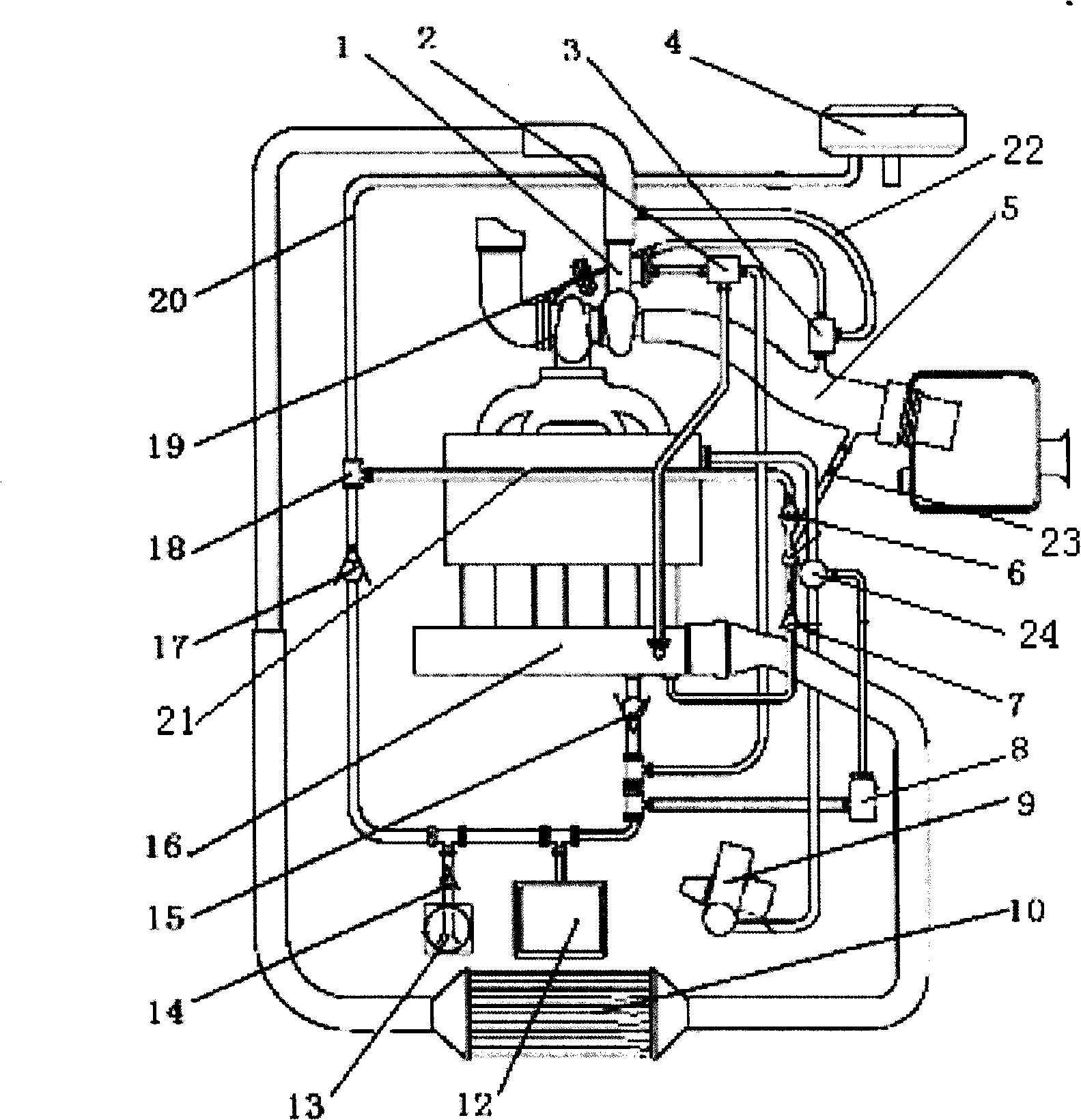
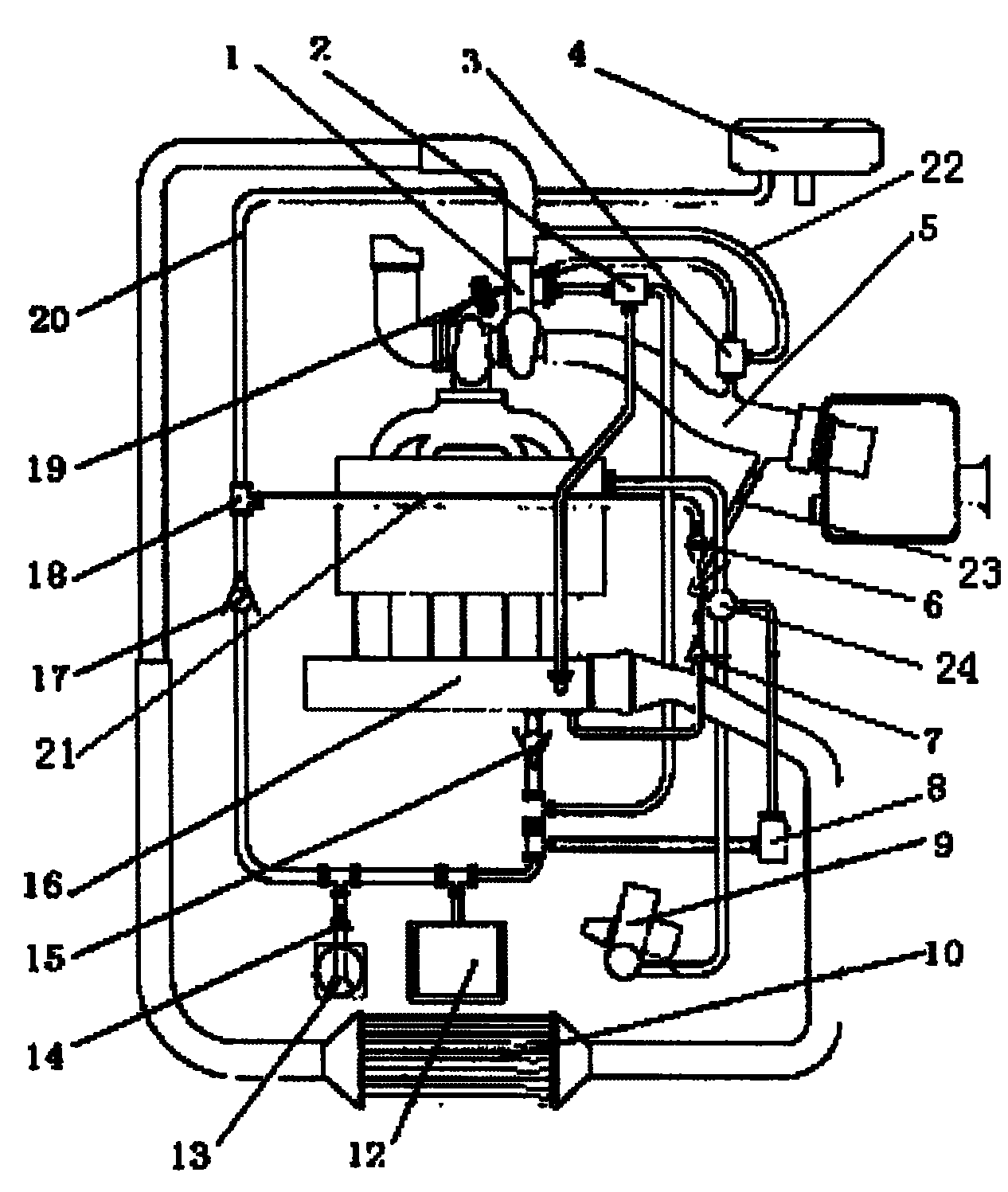
[0017] Example 1 in figure 1 Among them, a supercharged engine connects the outlet of the supercharger 1 to the intercooler 10 through a pipeline and then connects to the engine intake manifold 16 . Its vacuum system mainly includes the engine intake manifold 16 connected to the vacuum booster 4 through the first vacuum tube 20, and its feature is that a device for generating vacuum is provided on the pipeline between the engine intake manifold and the vacuum booster. The device includes a fourth one-way valve 15 and a vacuum tank 12

Embodiment 2

[0018] Embodiment 2 The device can also be a vacuum pump 13 . All the other are with embodiment 1.

Embodiment 3

[0019] Embodiment 3 The device can also be provided with a fourth one-way valve 15 connected to the vacuum tank 12 and the vacuum pump 13 in sequence on the first vacuum pipe 20 . All the other are with embodiment 1.


PUM


Abstract

A vacuum system for a supercharger engine is provided, which comprises an engine intake manifold and a vacuum booster connected with a first vacuum tube. The invention is characterized in that: a device for creating the vacuum degree, which comprises an one-way valve and a vacuum tank, is positioned on the pipeline between the engine intake manifold and the vacuum booster. The device can be arranged as a vacuum pump. The system also comprises a vacuum actuator for supercharger and a vacuum actuator control for a secondary air system. Because the vacuum pump is adopted for complementing the air and the vacuum tank stores the gas and is provided with a plurality of one-way valve, the invention is able to assure the flow of vacuum degree in fixed direction, ensure reverse sealing and realizethe switching function. in addition, by controlling a plurality of electromagnetic valves and vacuum pump via ECU as well as utilizing the vacuum storage function of the vacuum tank, the engine and the vacuum control system of the invention can work more reliably.

Description

technical field [0001] The invention relates to an engine vacuum system, in particular to a booster engine vacuum system. When the supercharged engine cannot generate the necessary vacuum, the ECU controls to start the vacuum pump or use the vacuum stored in the vacuum tank to ensure the reliable operation of the system that requires vacuum. Background technique [0002] At present, the supercharged engine vacuum system mainly includes that the vacuum of the engine vacuum system is generated by the engine in the intake manifold and the intake hose, and is directly connected to the systems that require vacuum through pipelines to provide these systems. With the development of today's engine technology and the adoption of advanced technologies such as booster systems and secondary air systems, the engine intake manifold is under positive pressure (greater than atmospheric pressure) under most operating conditions, although the intake hose can still The degree of vacuum is gen...

Claims


Application Information

Patent Timeline
Patent Type & Authority Patents(China)
IPC IPC(8): F02M35/104F02B39/16F01N3/22B60T13/52
Inventor 沈恩华段景宏朱志鹏董钧如
Owner CHERY AUTOMOBILE CO LTD
Why Eureka
Try Eureka