Detecting device, detecting method, manufacturing method and pattern transferring method for photomask

An inspection device and inspection method technology, which are applied in the field of photomasks for liquid crystal device manufacturing and inspection devices for large photomasks, can solve the problem that the objective lens system and the movement amount of the object to be exposed cannot be simulated quantitatively and cannot be reproduced correctly. Exposure device focusing action exposure pattern, can not be simulated quantitatively, etc.

Active Publication Date: 2008-06-11
HOYA CORP
View PDF2 Cites 10 Cited by
  • Summary
  • Abstract
  • Description
  • Claims
  • Application Information

AI Technical Summary

Problems solved by technology

Therefore, in the conventional inspection apparatus that only moves and operates the imaging element in the direction of the optical axis to adjust the focus, the focusing operation of the exposure device and the exposure pattern obtained by the exposure device cannot be accurately reproduced, and the performance of a large photomask cannot be performed satisfactorily. Evaluation and Defect Inspection
[0015] That is, in an inspection device that only moves and operates an imaging element in the direction of the optical axis to adjust the focus, in an exposure device that reproduces the state in which the photomask is bent by its own weight on the inspection device before actual exposure image, so it is not possible to accurately evaluate the focus margin during exposure
Specifically, how to position the objective lens and the exposed body (transcribed body) each in the exposure apparatus in order to verify the focus margin allowed by photomask exposure cannot be quantitatively simulated.
[0016] In addition, in such an inspection device, it is impossible to quantitatively simulate the movement amount of the objective lens system and the object to be exposed when the exposure device using a large photomask is defocused.
Therefore, the existing inspection equipment is not suitable for the evaluation of the focus margin under exposure, or the inspection of gray-scale (gray-ton-n) masks with fine patterns where defocusing is intentionally generated.

Method used


Image

  • Detecting device, detecting method, manufacturing method and pattern transferring method for photomask
  • Detecting device, detecting method, manufacturing method and pattern transferring method for photomask
  • Detecting device, detecting method, manufacturing method and pattern transferring method for photomask

Examples


Embodiment Construction

[0126] Next, the best mode for carrying out the present invention will be described.

[0127] [Summary of the photomask inspection device of the present invention]

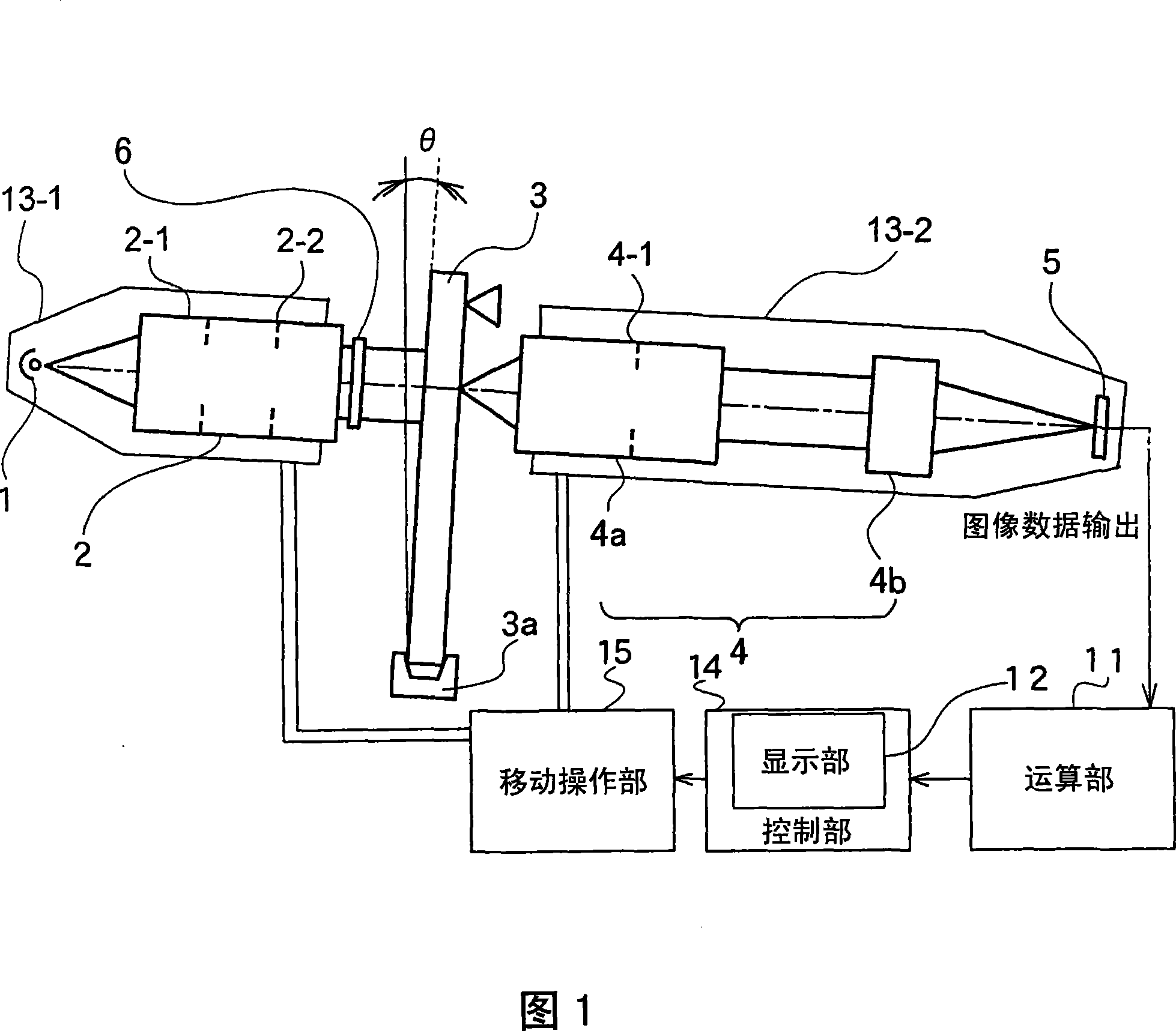
[0128] The photomask inspection device of the present invention is a device that can perform exposure conditions equal to those in an exposure device that performs exposure by using a photomask made of a transparent substrate, or according to the exposure device The exposure conditions obtained by simulating the exposure by the exposure device are transcribed onto the transcribed image, captured by the imaging unit, and obtained as light intensity distribution data. The exposure device is a device that transcribes the pattern formed in the photomask onto the transcribed body under certain exposure conditions. In addition, a target to be transcribed is, for example, a glass substrate coated with a resist or the like.

[0129] In addition, in this photomask inspection device, based on the light intensity distribut...


PUM


Abstract

In the photmask detecting device of the invention, the photomask holding part (3a) holds the photomask (3) which is irradiated with the light beam that comes from the light source (1) and has preset wavelength to the photomask (3) through the lamp optical system (2), and the image of the photomask (3) is shot by the camera shooting element (5) through the object lens system (4). The light axes ofthe lamp optical system (2), the object lens system (4) and the camera shooting element (5) are facilitated to consistent, the object lens system (4) and the camera shooting element (5) are moved andoperated independent with each other along the direction of the light axis to shoot the image of the photomask (3).

Description

technical field [0001] The present invention relates to a photomask inspection device and a photomask inspection method for inspecting the performance of a photomask for exposure, and more particularly to a photomask inspection device for a large photomask used in the manufacture of flat panel display (hereinafter referred to as FPD) devices and check method. Moreover, this invention relates to the manufacturing method of the photomask for liquid crystal device manufacture, and a pattern transfer method. Background technique [0002] Conventionally, in terms of performance inspection of photomasks, in Patent Document 1 (Japanese Unexamined Patent Publication No. Hei 5-249656), a method of detecting a photomask constituting an object by using an imaging device (hereinafter referred to as CCD) is described. A device that detects defects through the intensity distribution of illumination light. In this inspection device, the inspection light is condensed and irradiated onto a...

Claims


Application Information

Patent Timeline
Patent Type & Authority Applications(China)
IPC IPC(8): G03F1/00G03F7/20G03F7/00H01L21/027H01L21/66G01N21/956G03F1/84
CPCG01N21/956G02F1/1303G02F1/133516G03F1/84G03F7/7085
Inventor 吉田光一郎平野照雅
Owner HOYA CORP
Why Eureka
Try Eureka