Dc converter

A DC converter and converter technology, applied in the field of converters, can solve the problems of low utilization rate of converters, high output voltage ripple noise, and high voltage stress of isolation stage mains, achieving low ripple noise, good EMC, and reduced noise. The effect of small loss and cost

Active Publication Date: 2008-06-11
EMERSON NETWORK POWER CO LTD
View PDF2 Cites 35 Cited by
  • Summary
  • Abstract
  • Description
  • Claims
  • Application Information

AI Technical Summary

Problems solved by technology

[0006] The technical problem to be solved by the present invention is to provide a high-efficiency and dynamic response, better ripple noise and EMC cascaded compound topology low-voltage high-current DC converter

Method used


Image

  • Dc converter
  • Dc converter
  • Dc converter

Examples


Embodiment Construction

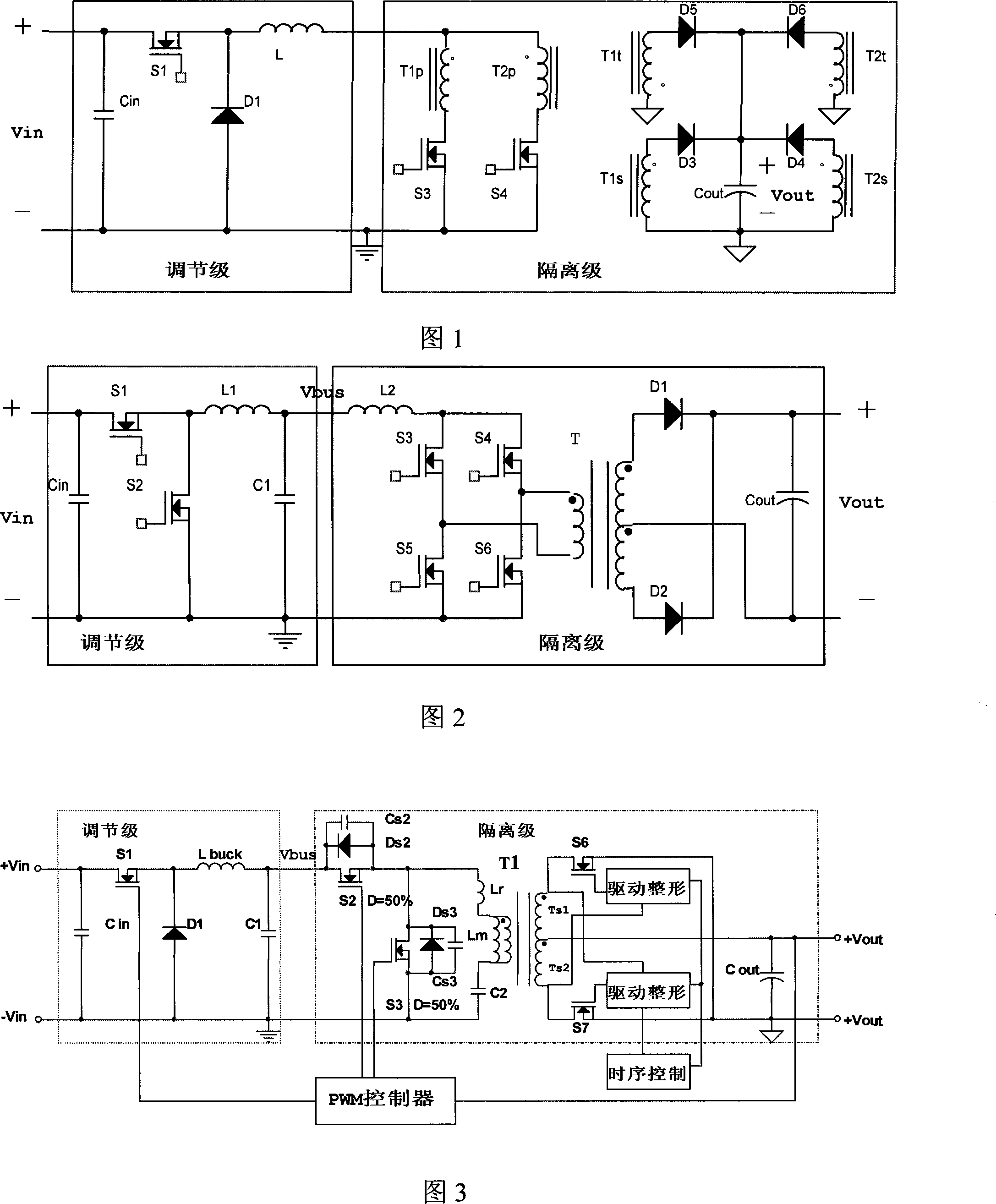
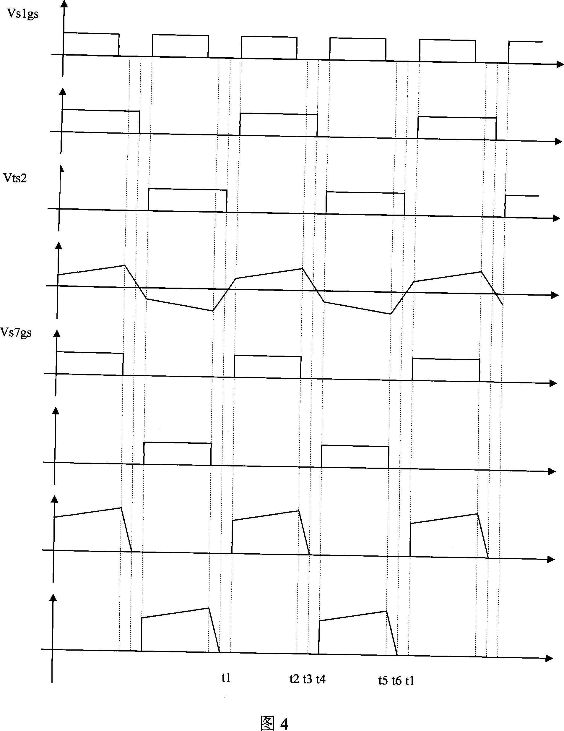
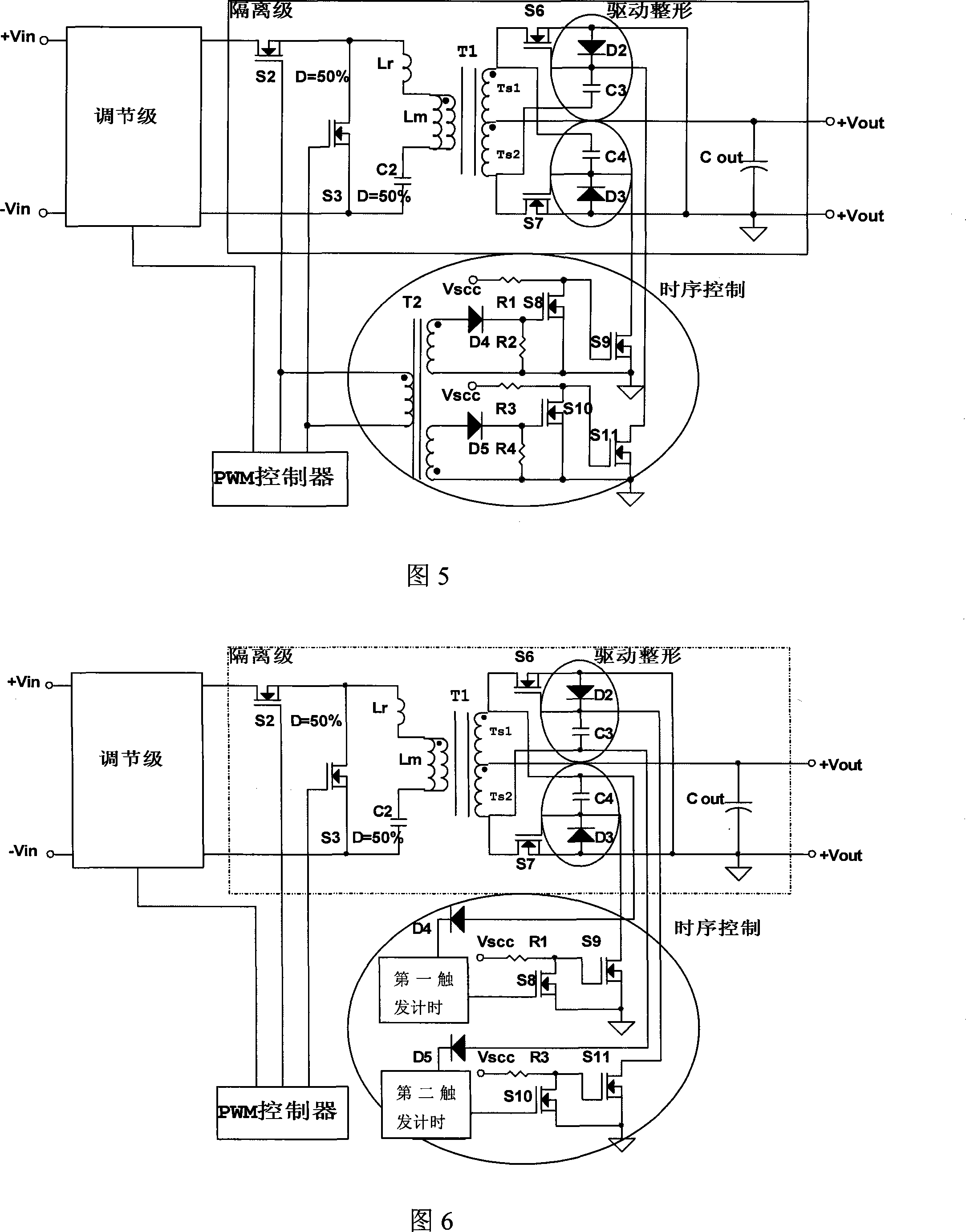
[0030] A DC converter according to the present invention includes a PWM controller, a regulation-level converter that receives a control pulse signal output by the PWM controller, and an isolation-level converter; the regulation-level converter adjusts the input voltage to a relatively stable bus voltage, The isolation-level converter converts the bus voltage into the required output voltage and transmits power for a fixed duty cycle. The secondary side of the transformer of the isolation-level converter is provided with a rectification circuit including two switching tubes. The rectification circuit includes two sets of diodes and The drive shaping circuit composed of capacitors is respectively connected to two switch tubes to form the first and second branches connected in parallel.

[0031] The regulating stage converter can be a buck circuit or a boost circuit. A symmetrical half-bridge circuit, a full-bridge circuit or a push-pull circuit can be used between the regulatio...


PUM


Abstract

The invention provides a DC converter which overcomes the shortcoming in the prior art that an isolating main voltage stress is high, the utilization rate of a transformer is low and the wave noise of the output voltage is high and so forth. The invention comprises a PWM controller, an adjustment converter for receiving an output controlling pulse signal of the PWM controller and an isolating converter; the adjustment converter can adjust the input voltage to a relatively stable bus voltage, the isolating converter is provided with a fixed air space ratio, which can transform the bus voltage into the output voltage required and transfer the power rate, the transformer auxiliary side of the isolating converter is provided with a rectifying circuit comprising two switch tubes, the rectifying circuit comprises two groups of driving wave-shaping circuit comprising two sets of diode and capacitors, which are respectively connected with the two switch tubes to form a staggered and parallel first branch and a second branch. The invention has the advantageous performance of high efficiency, dynamic reaction, better wave noise and EMC, which can meet the requirement of a low voltage current DC converter.

Description

technical field [0001] The present invention relates to a converter, more specifically, to a DC converter. Background technique [0002] With the development of high-integration and high-speed microprocessors, higher requirements are required for the power supply of the microprocessor. The output voltage of the module power supply has been reduced from the traditional 5V output to 1.5V, or even below 1V. The output voltage is increased by 10% and decreased by 20%; the output current is increased to tens of amperes, or even hundreds of amperes; the dynamic response current change rate is as high as tens of amperes / us. At the same time, the input voltage variation range of the module power supply is doubled, and the volume of the module power supply is as small as 1 / 16 brick. [0003] For this kind of low-voltage and high-current module power supply with wide input and wide output range, it is difficult for the traditional forward, half-bridge, full-bridge, and push-pull conv...

Claims


Application Information

Patent Timeline
Patent Type & Authority Applications(China)
IPC IPC(8): H02M3/28H02M3/335
Inventor 雷兴华宋凌锋
Owner EMERSON NETWORK POWER CO LTD
Why Eureka
Try Eureka