Geodetic target object and measuring system

A target object, geodetic surveying technology, applied in the directions of radio wave measurement systems, measurement rulers, measurement point markers, etc., to achieve the effect of improving signal strength and range, and increasing irradiance

Active Publication Date: 2008-06-11
LEICA GEOSYSTEMS AG
View PDF10 Cites 20 Cited by
  • Summary
  • Abstract
  • Description
  • Claims
  • Application Information

AI Technical Summary

Problems solved by technology

On the other hand, the patent addresses the problem of cross-coupling between the distance measuring beam and the receiving device on the reflector side

Method used


Image

  • Geodetic target object and measuring system
  • Geodetic target object and measuring system
  • Geodetic target object and measuring system

Examples


Embodiment Construction

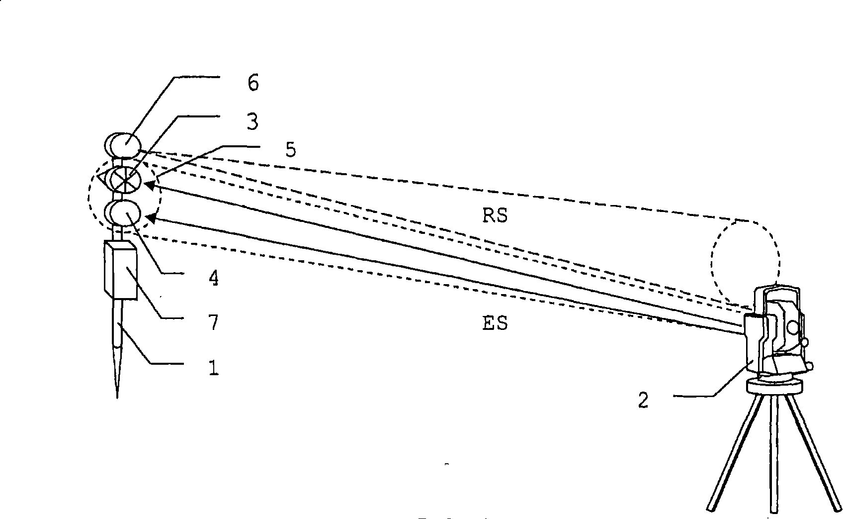
[0059] figure 1 A measuring system is shown which comprises a target object and a central measuring unit 2 according to the prior art. The target object comprises a plumb rod 1 on which is arranged a reflector 3 , a receiver 4 for radiation ES emitted from a measuring unit 2 and a transmitter 6 for transmitting back-reflected radiation RS. For controlling the separate components, a similar separate operating and control unit 7 can be used. The emitted radiation ES has a beam cross section 5 which, at relatively large distances, covers both the reflector 3 and the receiver 4 and thus allows simultaneous data transmission and measurement. However, this adequate coverage of these two components becomes worse at close range, and can even be completely absent, so that the target object cannot be measured or transmitted to the target object at a distance smaller than the threshold. Furthermore, the transmitter 6 must emit the retroreflected radiation RS with a divergence which ens...


PUM


Abstract

Disclosed is a geodetic target object comprising at least one reflector surface, a receive channel with a detector (18) for receiving electromagnetic radiation (ES) transmitted by a measuring unit (2''), and a transmit channel with a radiation source (13'). The associated transmission port and/or reception port is/are integrated into the reflector surface or is/are embodied so as to adjoin the reflector surface such that radiation (RS) that is modulated for transmitting data can be transmitted in the direction of the measuring unit (2'') within the cross section (5'') of the radiation (ES) generated by the measuring unit (2'').

Description

technical field [0001] The invention relates to a geodetic object according to the preamble of claim 1 , a modular component for such a geodetic object, and a method for transmitting data in geodetic surveying for determining the position of a geodetic object. Background technique [0002] In many geodetic applications, position measurements are made by placing specially designed target objects at the measurement location. The target object usually comprises a plumb rod with visible markings or a reflector for defining the measurement path or measurement position. A total station with distance and angle measurement or a theodolite is usually used as the central measuring unit for the measurement, and a relatively large number of target objects can also be measured by means of the central unit, which requires identification of the target objects. In such measuring tasks, numerous pieces of data, commands, languages ​​and other pieces of information are transferred between th...

Claims


Application Information

Patent Timeline
Patent Type & Authority Applications(China)
IPC IPC(8): G01C15/00G01C15/06G01S19/49G01S19/51
CPCG01C15/002G01C15/06
Inventor 于尔格·欣德林克劳斯·施奈德
Owner LEICA GEOSYSTEMS AG
Why Eureka
Try Eureka