Lacrimal duct water-spreading equipment and lacrimal duct bougie therewith
A technology of lacrimal duct and bougie, which is applied in wound drainage devices, suction instruments, eye surgery, etc., and can solve problems such as cumbersome operations
- Summary
- Abstract
- Description
- Claims
- Application Information
AI Technical Summary
Problems solved by technology
Method used
Image
Examples
Embodiment 1
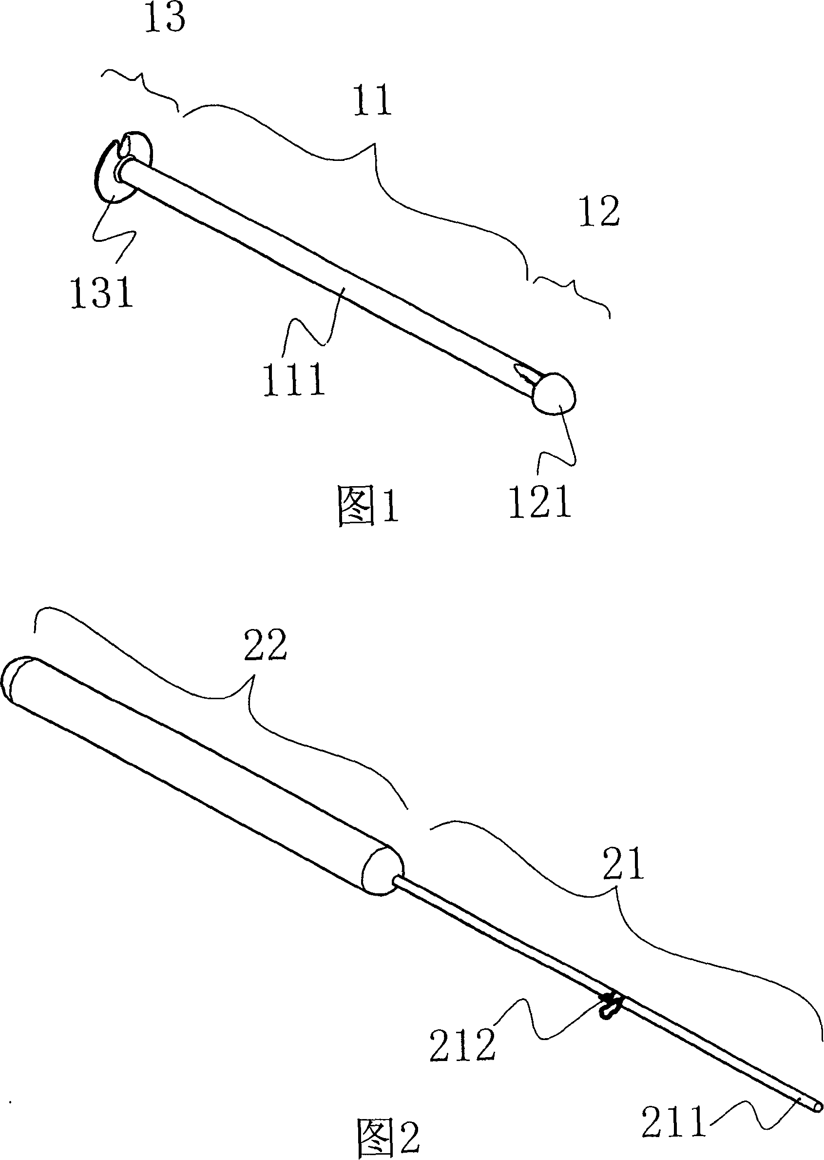
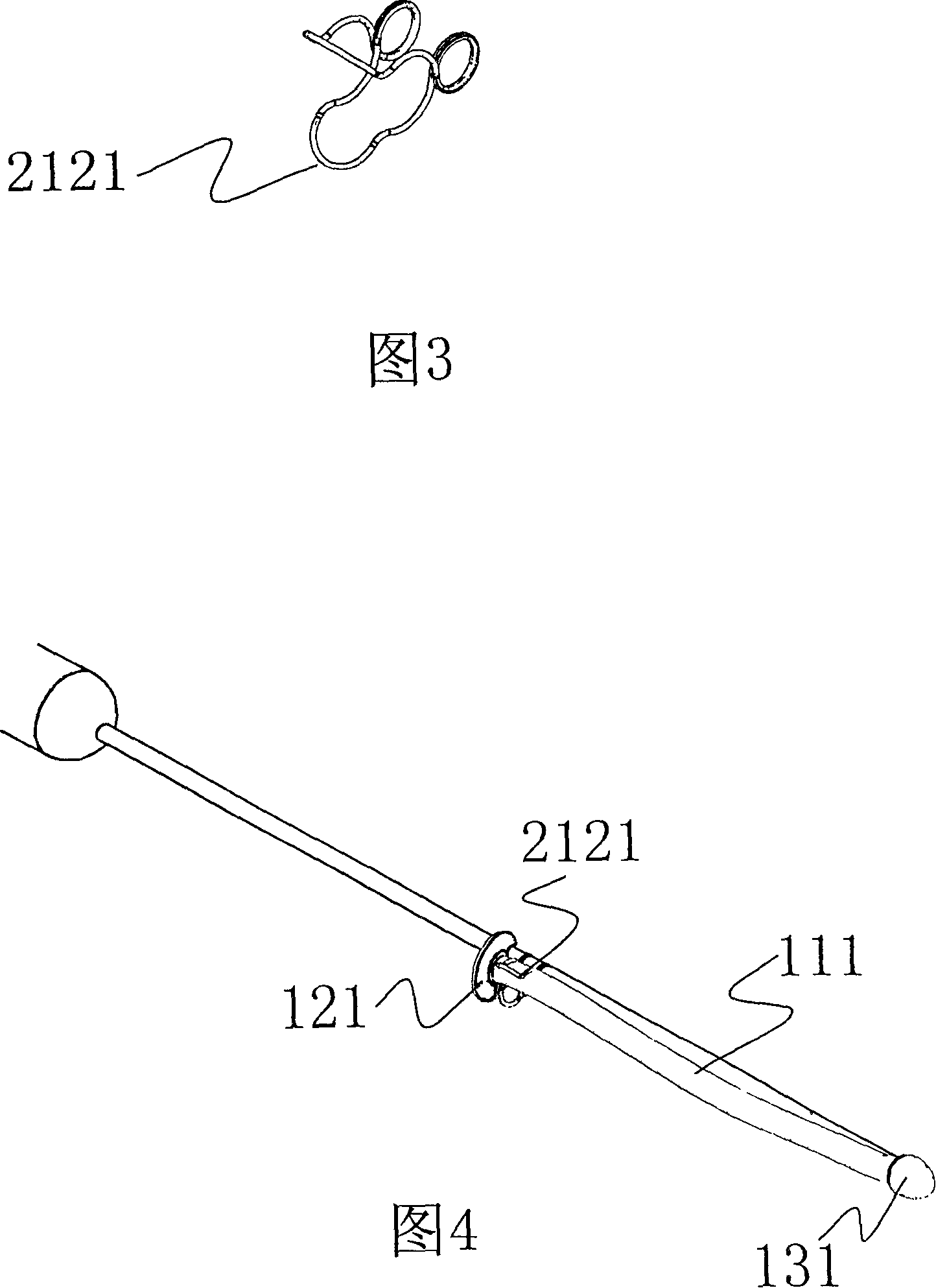
[0044] See Figures 1-4 and the figures, the lacrimal duct drainage device disclosed in this example includes a drainage part 111 made of a solid cylindrical soft strip with a cross-sectional diameter of 0.1-3.0 mm, preferably about 1 mm, and a drainage part connected to the drainage part. There is a blunt pouch-shaped connection portion 121 at the top end of the drainage portion, and a nail cap-shaped holding portion 131 connected to the other end of the drainage portion. The holding part can be a nail cap structure, an umbrella structure, or a strip shape or a flat strip shape similar to the section of the lacrimal duct. The latter two structures must be knotted with an appropriate size before use and the excess part should be cut off. The advantage is that the length of the drainage device can be temporarily determined by the difference in the position of the knot during use. When the device is put into the lacrimal duct, the holding part stays outside the lacrimal duct, so ...
Embodiment 2
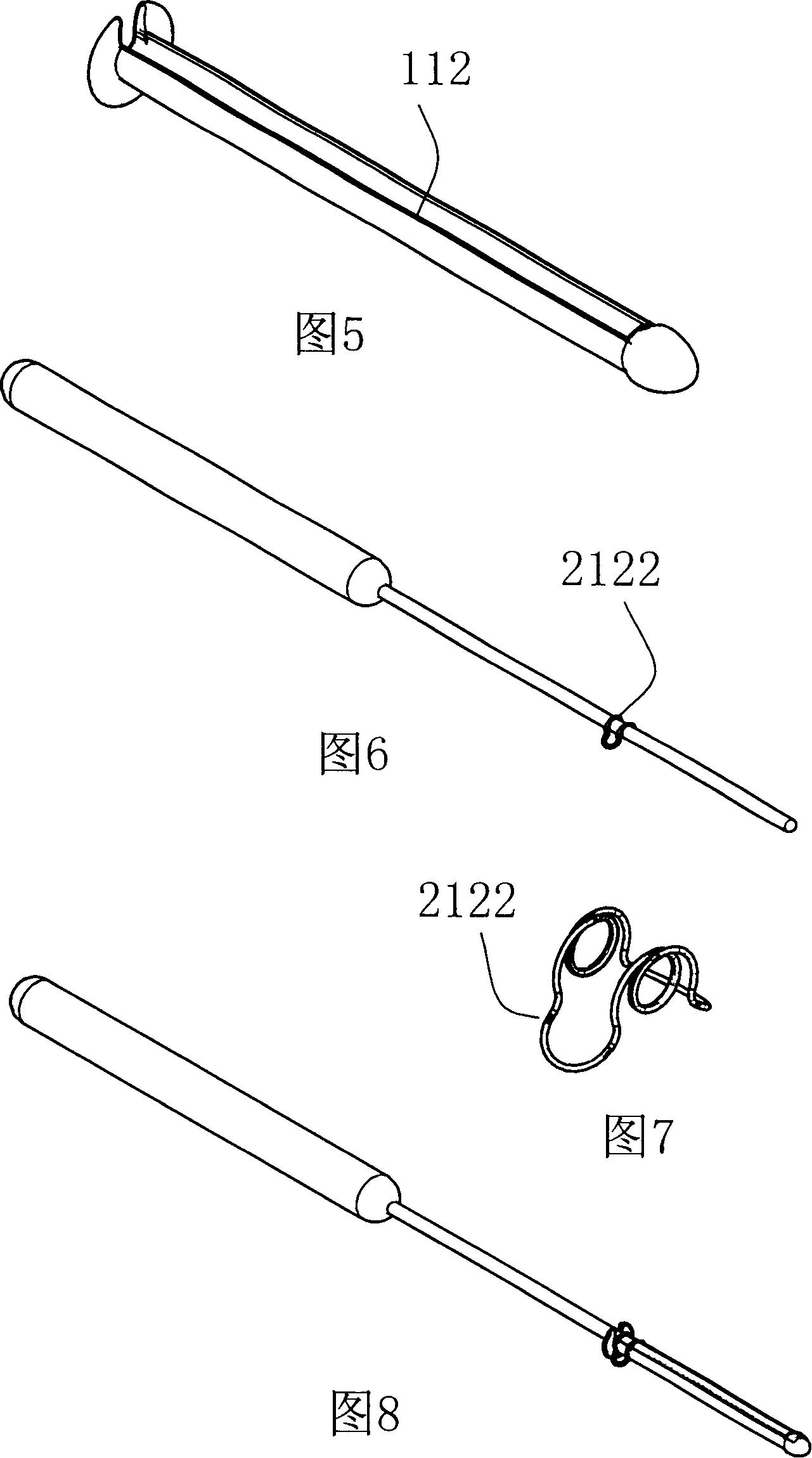
[0046] See Figure 5-12, on the basis of Example 1, a deep groove 112 is set along the long axis of the drainage device. The cross-sectional size of the deep groove is slightly larger than the cross-section of the bougie probing part, and can be in the shape of "C" or " U" shape, straight to the pouch of the connecting part. When the holding part of the drainage device is in the shape of an umbrella or a nail cap, the deep groove runs through the holding part in the shape of an umbrella or a nail cap. The connection and fixing method between the drainage device and the bougie is roughly the same as that of Embodiment 1, except that the bougie is located in the deep groove, and the fixing device on the bougie is another kind of spring clip 2122, or only a rough surface 21231 is provided at a corresponding position. , and bind the drainage device and the bougie with a binding wire 21232 of appropriate strength. The improvement of embodiment 2 makes the combination of the drainag...
Embodiment 3
[0048]As shown in Figures 13-17, the drainage part and connection part of Embodiment 2 are improved, and the drainage part is changed to a solenoid structure 113 formed by moving and rotating a quasi-circular or approximately arcuate section, and the connection part is changed to have a The flat dimple 1221 matched with the probe end of the bougie has a head-like structure 122 with a blunt tip at the top, the probe end of the bougie is correspondingly set as a blunt round shovel-shaped structure 2112, the fixing device is a fixing clip 2124, and the setting of the holding part is compatible with the bougie through holes 1311 . In a natural state, the outer diameter of the helix can be larger than the inner diameter of the lacrimal duct. Before the drainage device is put into the lacrimal duct, the bougie is inserted into the flat socket of the connecting part through the solenoid, and then the solenoid is tightened to fix the holding part and the bougie. At this point, the ou...
PUM
 Abstract
Description
Claims
Application Information
 - R&D
- Intellectual Property
- Life Sciences
- Materials
- Tech Scout
- Unparalleled Data Quality
- Higher Quality Content
- 60% Fewer Hallucinations
Browse by: Latest US Patents, China's latest patents, Technical Efficacy Thesaurus, Application Domain, Technology Topic, Popular Technical Reports.
© 2025 PatSnap. All rights reserved.Legal|Privacy policy|Modern Slavery Act Transparency Statement|Sitemap|About US| Contact US: help@patsnap.com


