Screwdriver

A screwdriver and casing technology, which is applied in the field of screwdrivers, can solve the problems of screw fastening operation constraints, increase in overall width, and reduce workability, etc., to achieve excellent workability, compactness, and space-saving effects

Inactive Publication Date: 2008-06-18
MAKITA CORP
View PDF1 Cites 6 Cited by
  • Summary
  • Abstract
  • Description
  • Claims
  • Application Information

AI Technical Summary

Problems solved by technology

[0005] However, in the screwdriver provided with an intermediate shaft as described above for deceleration, for example, as shown in FIG. The mechanism part 53 is often provided protruding from the side of the case 50
Therefore, the overall width increases, thereby restricting the screw fastening w

Method used


Image

  • Screwdriver
  • Screwdriver
  • Screwdriver

Examples


Embodiment Construction

[0017] Embodiments of the present invention will be described below with reference to the drawings.

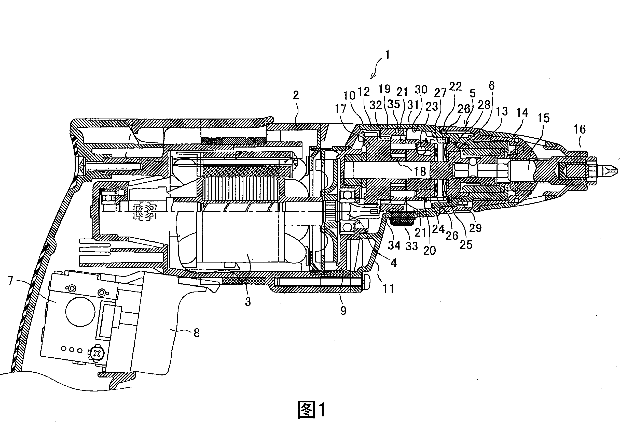
[0018] Fig. 1 is a longitudinal sectional view showing an example of a screwdriver. The screwdriver 1 accommodates a motor 3 at the rear (left side of Fig. 1 ) of a main body casing 2, and is connected to a front casing 5 in front thereof, and the front casing 5 An output shaft 6 is accommodated above the motor shaft 4 of the motor 3, and the output shaft 6 can move back and forth in the axial direction. 7 is the switch of motor 3, and 8 is the trigger that makes switch 7 connected.

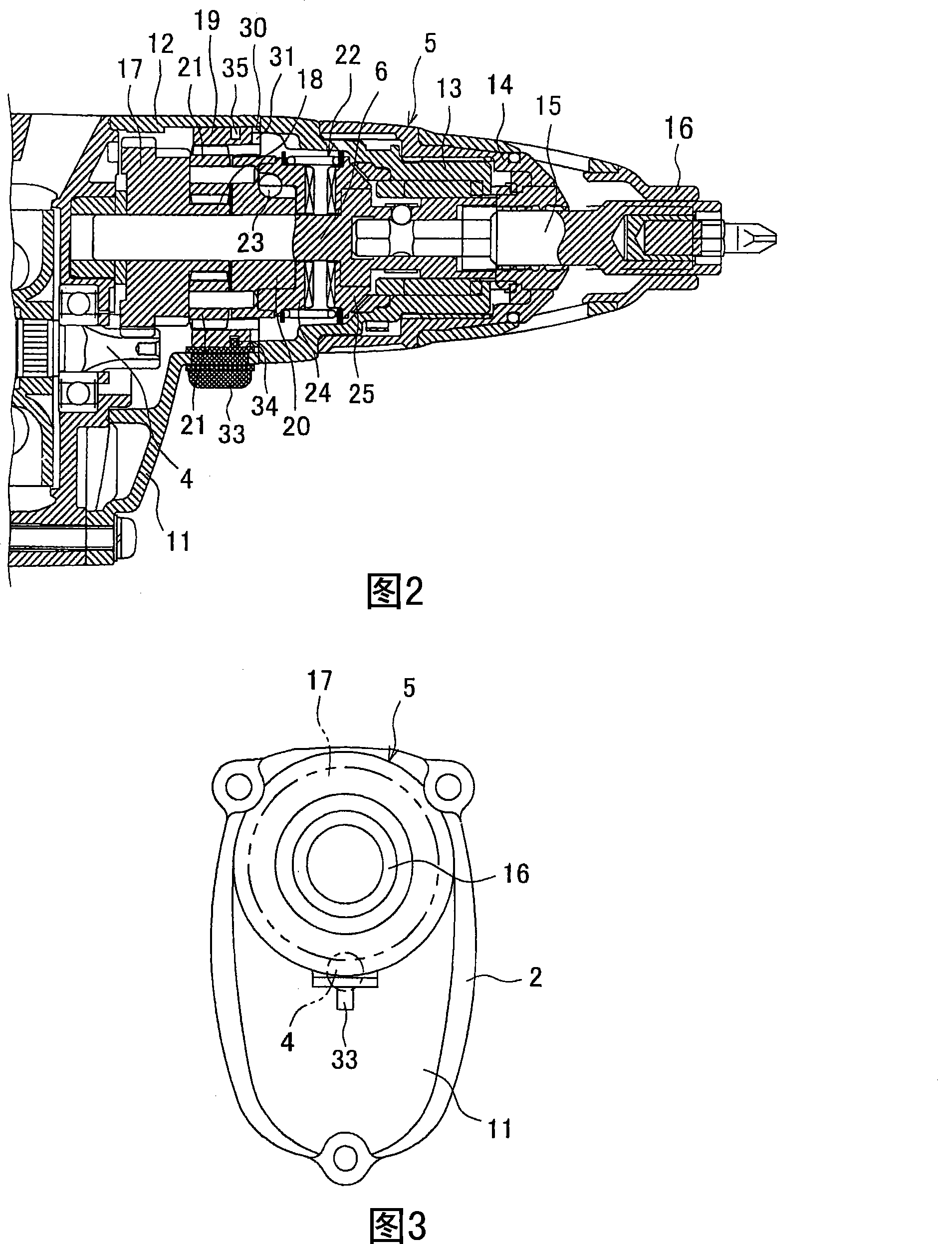
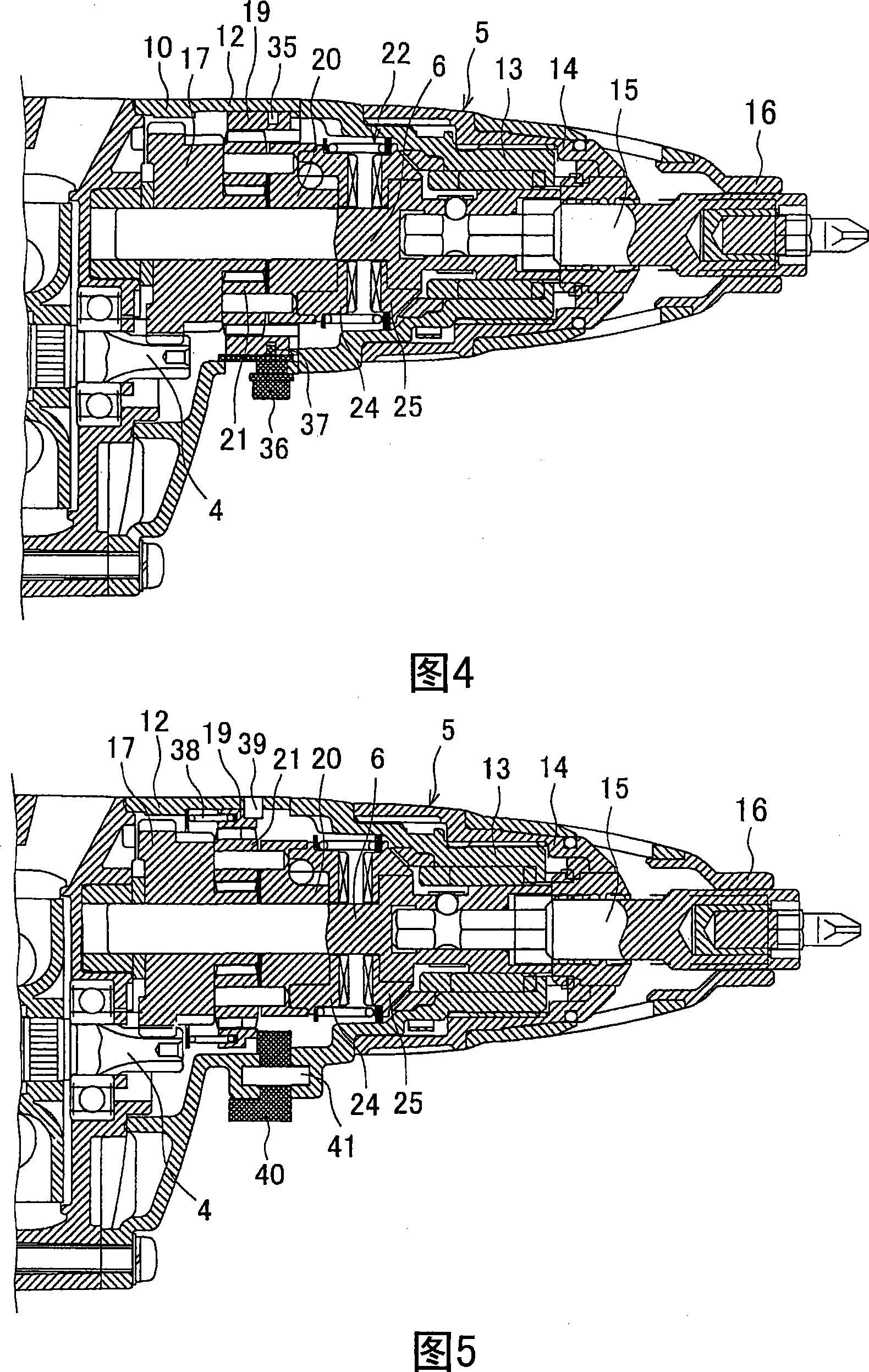
[0019] The front housing 5 is formed by sequentially installing a gear case 10, a front end sleeve 13, and a lock ring 14 on the bearing housing 9 which pivotally supports the rear ends of the motor shaft 4 and the output shaft 6 respectively, wherein the gear case 10 has a covering bearing The cover portion 11 of the lower half of the housing 9 is formed with a cylindrical portion 12 above; the...


PUM


Abstract

The present invention provides a screw driver, realising compaction of the case and proceeding deceleration and two stage speed change at the same time. A planetary gear frame (20) is between a second gear (17) and a clutch mechanism (22), the planetary gear frame (20) has a planetary gear revolving motion in the inner gear (19) around a rotary center of the output (18) of the second gear (17), in another aspect, the inner gear is set by rotating in the front case (5) and moving between the back position and the front position, in the back position, the inner gear (19) is clamped with the output (19) to directly connect the second gear (17) and the planetary gear frame (20), in the front position, the inner gear (19) is separated with the output (18), and clamped with the clamping part (30), to limit rotation, a gear shift button (33) is set in the front and the back for switching the inner gear on the front case.

Description

technical field [0001] The invention relates to a screwdriver for screw fastening. Background technique [0002] In a screwdriver, as shown in Patent Document 1, it is known that an intermediate shaft is arranged in parallel below it between the motor and an output shaft provided with a clutch mechanism, and that a first-speed gear arranged behind the intermediate shaft is meshed with the motor shaft. , the second-speed pinion gear provided in front of the intermediate shaft meshes with the final drive gear of the output shaft, so that the rotation of the motor shaft can be decelerated and transmitted to the output shaft. [0003] In addition, here, in order to perform two-stage shifting of the output shaft, the intermediate shaft can be moved in the front-rear direction through the shift lever provided on the lower surface of the housing, and behind the second-speed pinion, on the intermediate shaft Another second speed pinion meshing with the final drive is rotatably moun...

Claims


Application Information

Patent Timeline
IPC IPC(8): B25B21/00
CPCB25B21/00B25F5/001
Inventor 柴田美德田中孝治
Owner MAKITA CORP
Why Eureka
Try Eureka