
Control apparatus for eliminating reversing shake of dbl act gas cylinder

A double-acting cylinder and control device technology, applied in the direction of fluid pressure actuators, electrical components, semiconductor/solid-state device manufacturing, etc., can solve the problems of chip 6 out of position, adverse consequences, etc., to eliminate jitter, eliminate rapid expansion and contraction, The effect of meeting the requirements

Active Publication Date: 2008-06-18
BEIJING NAURA MICROELECTRONICS EQUIP CO LTD
View PDF0 Cites 12 Cited by
  • Summary
  • Abstract
  • Description
  • Claims
  • Application Information

AI Technical Summary

Problems solved by technology

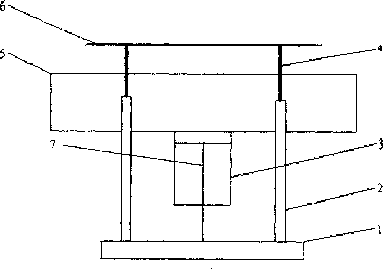
Then it transitions to smooth operation, which will cause the wafer 6 to be out of position due to the instant separation from the rising pin 4, resulting in adverse consequences.

Method used


Image

  • Control apparatus for eliminating reversing shake of dbl act gas cylinder
  • Control apparatus for eliminating reversing shake of dbl act gas cylinder
  • Control apparatus for eliminating reversing shake of dbl act gas cylinder

Examples


Embodiment 1

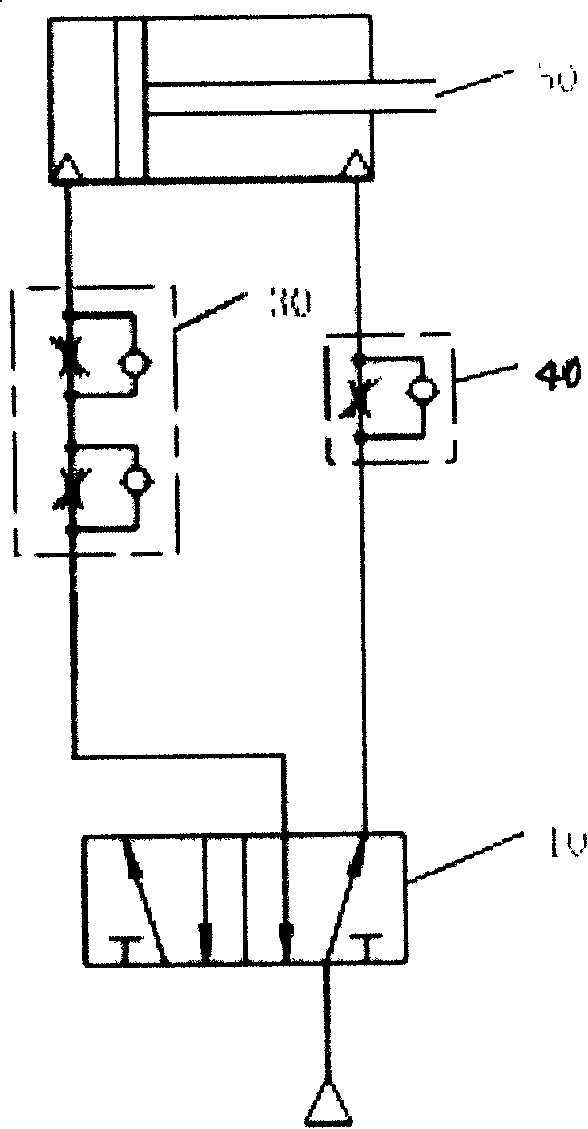
[0027] The control device for eliminating the reversing vibration of the double-acting cylinder provided by the present invention is an improvement on the prior art, such as image 3 As shown, the air inlet of the two-position five-way solenoid valve 10 as a reversing valve is connected to the air source, and an outlet of the two-position five-way solenoid valve 10 is connected with a two-way speed regulating valve 30, and the two-way speed regulating valve 30 The other end is connected to an intake port of the double-acting cylinder 50 . When the wafer is transferred from the highest position to the lowest position, the air flow flows out from an outlet of the two-position five-way solenoid valve 10 and enters the rodless chamber of the double-acting cylinder 10 through the two-way speed regulating valve 30. In order to prevent the double-acting cylinder 50 from starting When the piston rod of the cylinder "extends rapidly", the flow rate of the air flow in the pipeline can b...

Embodiment 2

[0030] This example is a preferred embodiment of the present invention. In order to ensure that the operation process of the double-acting cylinder is stable and the operation time can meet the requirements, a speed change device is added to the control device, such as Figure 4 As shown, in the control air circuit of the wafer lifting device in the first embodiment, a transmission device is added, and the transmission device includes two first two-position two-way solenoid valves 21 and second two-position two-way solenoid valves 22. One two-position two-way solenoid valve 21 is installed on the air pipeline provided with a two-way speed regulating valve 30, and is connected in series with the two-way speed regulating valve 30, and the second two-position two-way solenoid valve 22 is connected in parallel with the two-way speed regulating valve 30 and the two-way speed regulating valve 30 connected in series. The two ends of the first two-position two-way solenoid valve 21. W...


PUM


Abstract

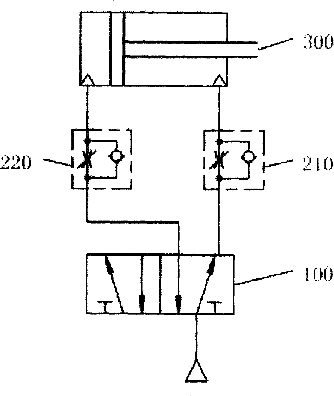
The invention discloses a control device for eliminating the reverse judder of a double-acting air cylinder. The device is connected with the two air inlet ends of the double-acting air cylinder to control the movement of the cylinder. The device comprises a reversing valve, a bidirectional governing valve and a throttle valve. The inlet opening of the reversing valve is connected with air supply. One outlet of the reversing valve is connected with one air inlet end of the double-acting air cylinder by the bidirectional governing valve. The other outlet of the reversing valve is connected with the other air inlet end of the double-acting air cylinder by the throttle valve. In addition, the control device includes a detecting unit and an automatic control unit which are used for detecting the operation situation of the double-acting air cylinder and controlling the operation of the double-acting air cylinder. When the air cylinder is started, the rapid extension of a cylinder rod, namely the reverse judder of the double-acting air cylinder, can be eliminated by the control device. The invention can improve the stability and the reliability of the air cylinder and can not effect the running time requirement of the double-acting air cylinder at the same time.

Description

technical field [0001] The invention relates to the technical field of pneumatic control in the field of mechanical design, in particular to a control device for eliminating commutation vibration of a double-acting cylinder. Background technique [0002] Pneumatic control is often used in mechanical design. Pneumatic control is widely used in automatic machinery because of its flexible design and convenient control. However, in the pneumatic control, the "jitter" phenomenon of the driving device, especially the reversing of the double-acting cylinder, has a great influence on the accuracy and reliability of the pneumatic control. The application of pneumatic control in semiconductor processing equipment will be described in detail below. [0003] In the process of semiconductor processing, the cleanliness of the etching environment is very high. The mechanical structure will produce impurity particles that pollute the environment due to wear and other reasons, and the hydra...

Claims


Application Information

Patent Timeline
Patent Type & Authority Applications(China)
IPC IPC(8): F15B21/00F15B13/044F15B15/26H01L21/306
Inventor 王志升
Owner BEIJING NAURA MICROELECTRONICS EQUIP CO LTD
Learn More