Fixed structure

A fixed structure and fixed part technology, applied in the direction of support structure installation, digital processing power distribution, etc., can solve the problems of switching circuit board 50 falling or collision, waste of manpower and working hours, etc., to achieve simple operation, reduce manpower and working hours the wasteful effect of

Active Publication Date: 2008-06-18
SHANGHAI MUNICIPAL ELECTRIC POWER CO
View PDF0 Cites 2 Cited by
  • Summary
  • Abstract
  • Description
  • Claims
  • Application Information

AI Technical Summary

Problems solved by technology

[0003] Please refer to FIG. 3 , which is a schematic diagram of a fixed structure combination of a conventional adapter circuit board. As shown in the figure, when the adapter circuit board 50 is assembled and fixed on the housing 40 of the electronic device in a screw-lock manner, multiple The screws 60 are fixed one by one, that is, first align the screw holes 51 on one side of the adapter circuit board 50 with the screw holes 41 on one side of the housing 40, and then lock the screws 60 in sequence, and then the adapter circuit board The screw holes 51 on the other side of the board 50 are aligned with the screw holes 41 on the other side of the housing 40 and the screws 60 are sequentially locked, so as to lock the adapter circuit board 50 to the housing 40 of the electronic device However, since the adapter circuit board 50 must be locked one by one with a single screw when locking, and when the adapter circuit board 50 is to be disassembled, it must be removed one by one Screws are used to disassemble, and the transfer circuit board 50 must be prevented from falling or colliding, and manpower assistance is required to overcome the above-mentioned problems in the assembly process, which results in a waste of manpower and working hours.

Method used


Image

  • Fixed structure
  • Fixed structure
  • Fixed structure

Examples


Embodiment Construction

[0033] Embodiments of the present invention are described below through specific examples, and those skilled in the art can easily understand other advantages and effects of the present invention from the content disclosed in this specification.

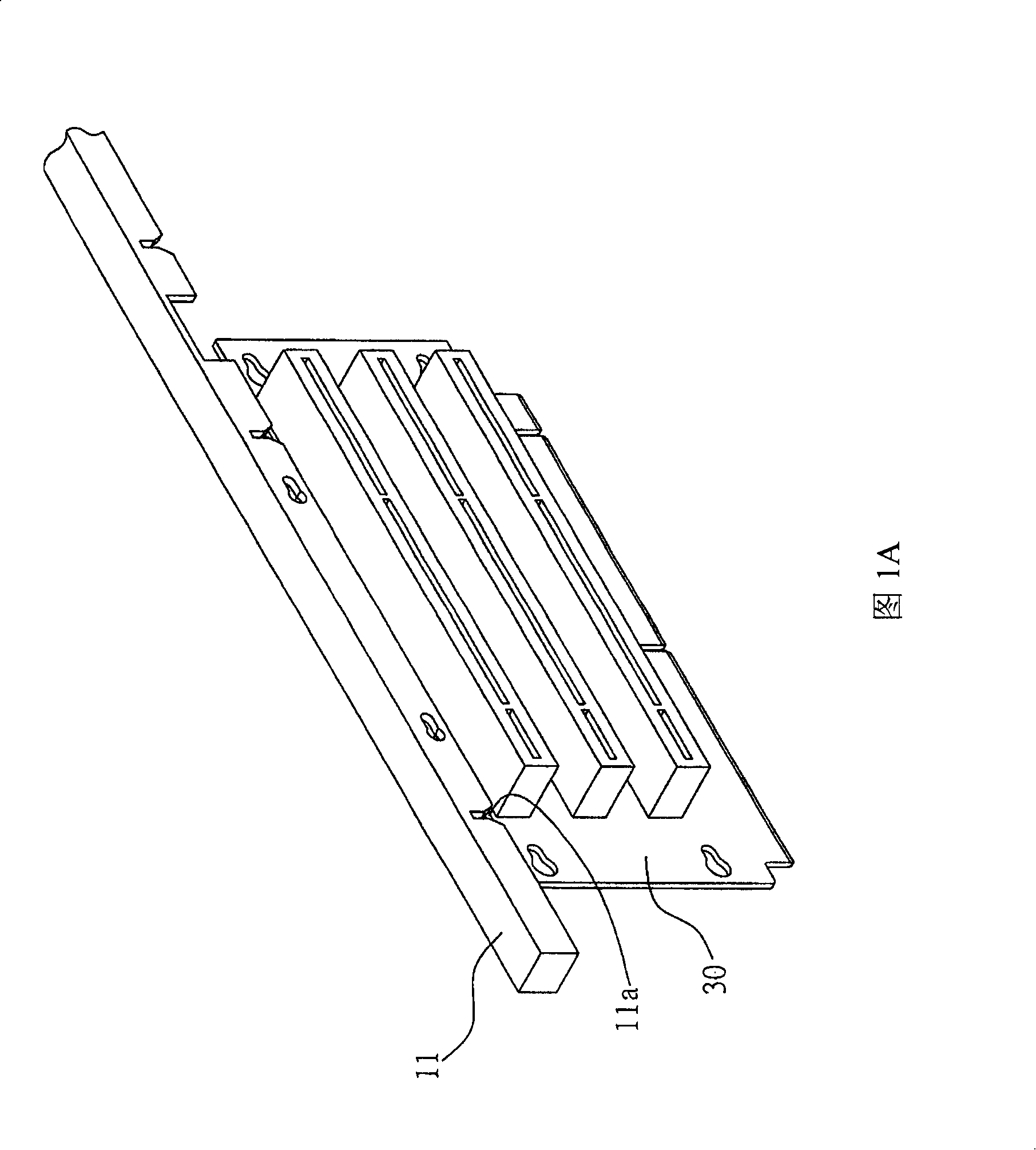
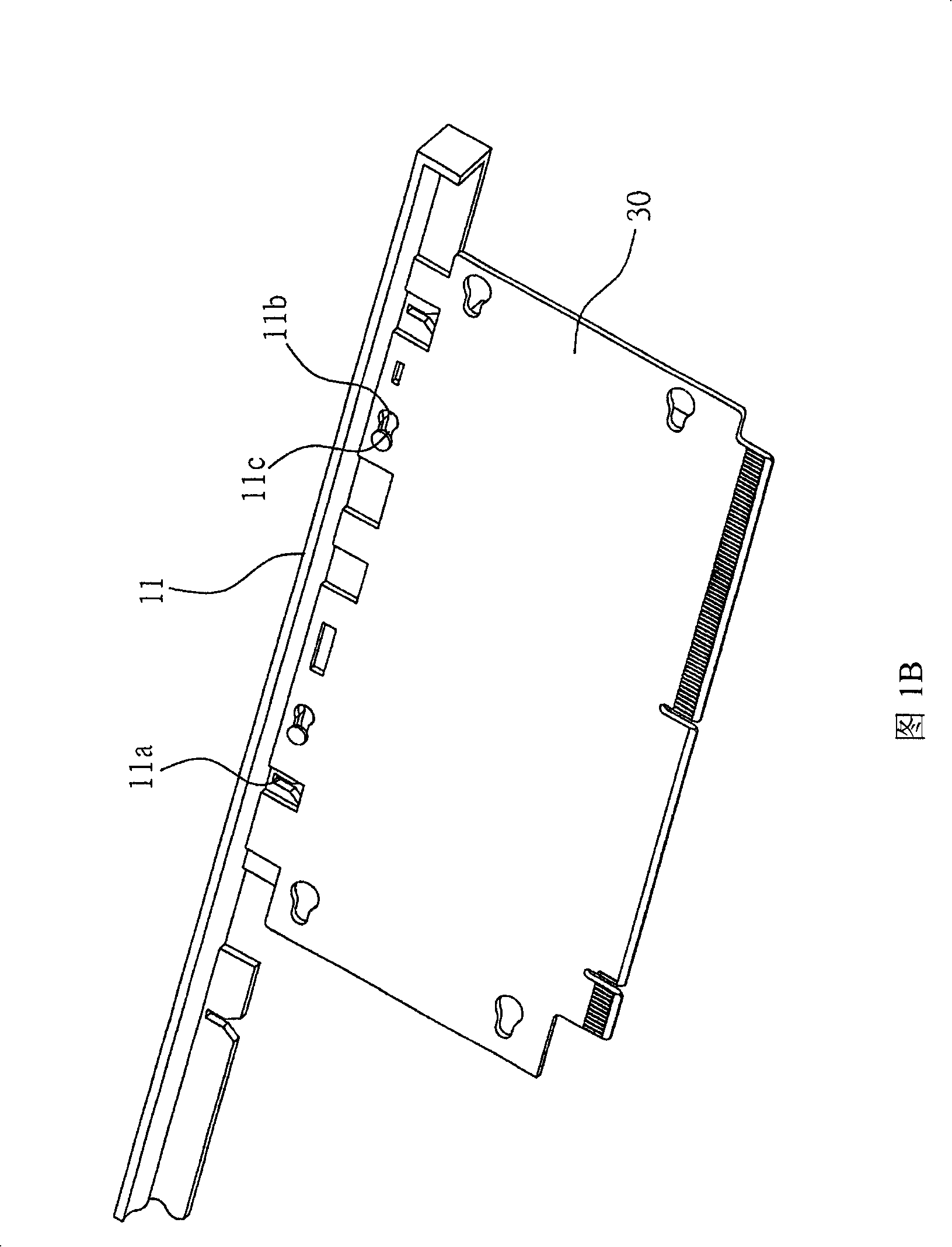
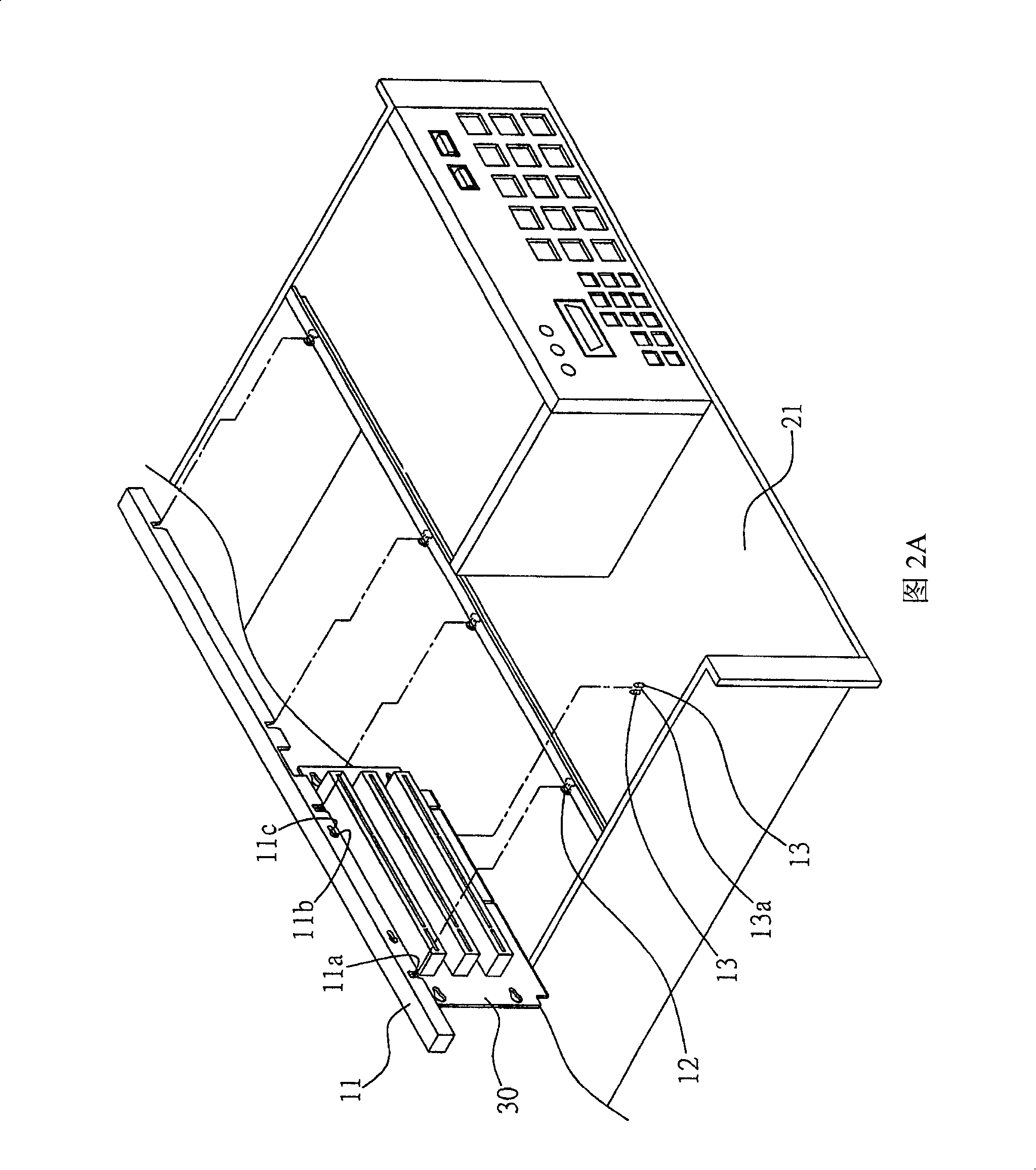
[0034] Please refer to Fig. 1A to Fig. 1B and Fig. 2A to Fig. 2B, which are schematic diagrams of the fixed bracket structure of the fixed structure, structural decomposition and combination diagrams of the fixed structure of the present invention, as shown in the figure: the fixed structure of the present invention includes The fixing bracket 11, the second fixing part 12 and at least two positioning parts 13 are used to fix the adapter circuit board 30 in the casing 20 of the electronic equipment, wherein the adapter circuit board 30 is a hard disk, an optical drive, a floppy drive or It is an adapter circuit board for other data access devices, etc.

[0035] The fixing bracket 11 is used to install the switching circuit board 30, ...


PUM


Abstract

The invention provides a fixed structure which is arranged on a casing. When a fixed bracket provided with a switching circuit board is fixed on the casing, a first fixing part which is arranged on the fixed bracket is block and fixed with a second fixing part which is arranged on the casing. At the same time, a plurality of capacity spaces formed by locating parts are arranged on the base of the casing, so the switching circuit board can be fixed in the capacity space and is further fixed on the casing. The invention is easy to be operated and can reduce the waste of manpower and man-hour when the present in assemble and disassemble. So the problems in the prior art that the assembly must be executed with tools and the problems of disassemble are avoided.

Description

technical field [0001] The invention relates to a fixing structure, in particular, to a fixing structure capable of fixing an adapter circuit board on a casing of an electronic device. Background technique [0002] Since in the casing assembly process of electronic equipment, it is often necessary to assemble or replace the transfer circuit board of the data access device (such as: hard disk, floppy drive, optical drive) in the case of the electronic device, the conventional transfer circuit board Most of the fixing methods are to fix the adapter circuit board on the casing of the electronic equipment by means of screw locks. [0003] Please refer to FIG. 3 , which is a schematic diagram of a fixed structure combination of a conventional adapter circuit board. As shown in the figure, when the adapter circuit board 50 is assembled and fixed on the housing 40 of the electronic device in a screw-lock manner, multiple The screws 60 are fixed one by one, that is, first align the...

Claims


Application Information

Patent Timeline
Patent Type & Authority Applications(China)
IPC IPC(8): G06F1/18H05K7/14
Inventor 郭合文
Owner SHANGHAI MUNICIPAL ELECTRIC POWER CO
Why Eureka
Try Eureka