Camshaft drilling device

A technology for drilling devices and camshafts, applied in positioning devices, boring/drilling, drilling/drilling equipment, etc., can solve problems such as the influence of processing efficiency, the amplification of processing errors, and the complexity of clamping and positioning operations , to avoid positioning interference

Pending Publication Date: 2019-05-10
SHENGRUI TRANSMISSION
View PDF0 Cites 1 Cited by
  • Summary
  • Abstract
  • Description
  • Claims
  • Application Information

AI Technical Summary

Problems solved by technology

In the prior art, the center hole of the camshaft is processed through the claw plate on the lathe to fix the journal of the camshaft, the rotation of the main shaft drives the camshaft to rotate, and the fixed drill bit is fed to the end face of the camshaft to realize the machining of the center hole, but this The processing method only ensures the fixation of one side of the camshaft, and cannot guarantee the levelness of the center hole, which easily causes the error amplification of the subsequent processing process, and the clamping and positioning operation is complicated, which has a great impact on the processing efficiency

Method used


Image

  • Camshaft drilling device
  • Camshaft drilling device
  • Camshaft drilling device

Examples


Embodiment 1

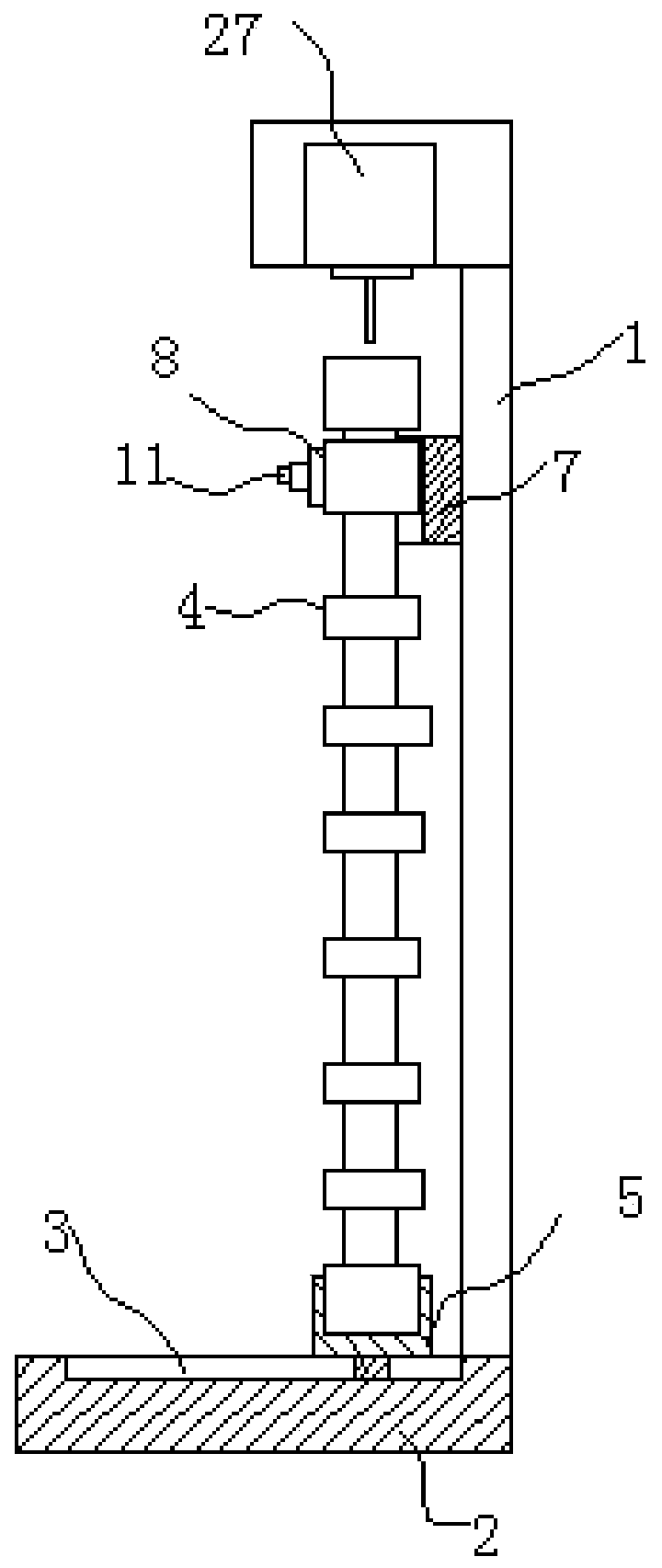
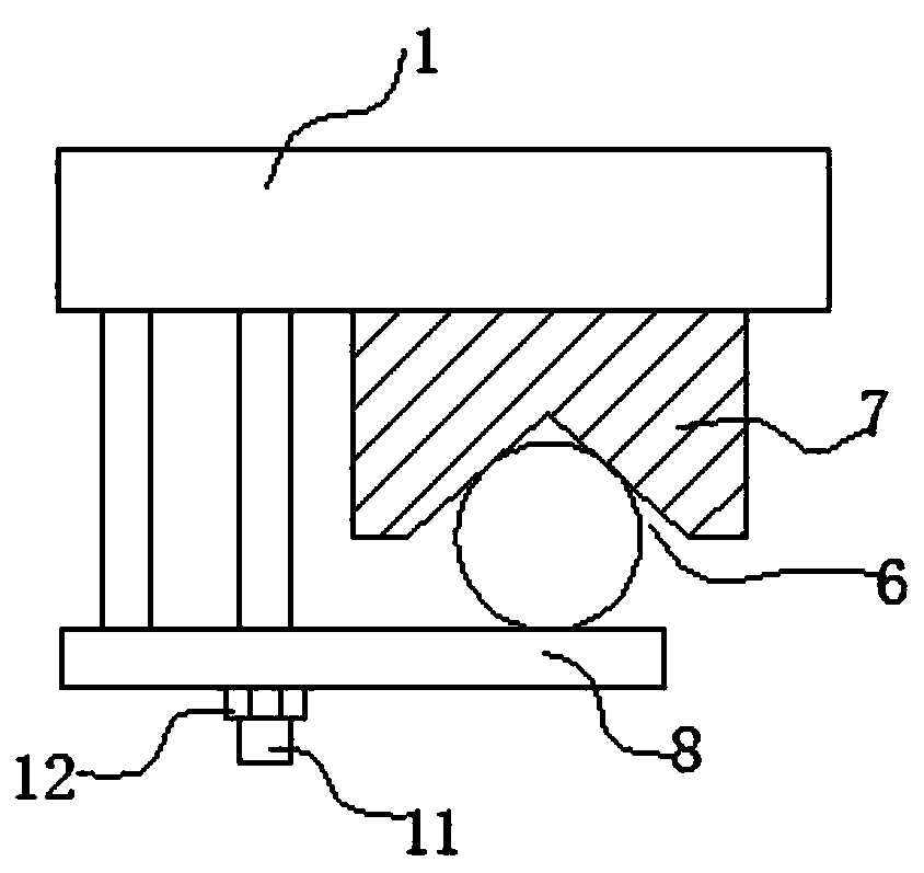
[0017] Such as Figure 1 to Figure 2 As shown, a camshaft drilling device includes a frame 1, the lower end of the frame 1 is fixedly mounted with a base 2, and the upper surface of the base 2 is provided with a guide groove 3 extending transversely or longitudinally. A positioning sleeve 5 sleeved on the lower end of the camshaft 4 is movably installed in the guide groove 3, and the inner peripheral surface of the positioning sleeve 5 is close to the outer peripheral surface of the camshaft 4 and is in clearance fit with the lower end of the camshaft 4. , the frame 1 is also provided with a camshaft positioning device located above the positioning sleeve 5 , and the frame is also provided with a drilling device 26 located above the upper end of the camshaft 4 . The drilling device 27 can be a working head of a vertical drilling machine, and the column of the vertical drilling machine is fixedly connected with the frame. The camshaft locating device is positioned above the lo...

Embodiment 2

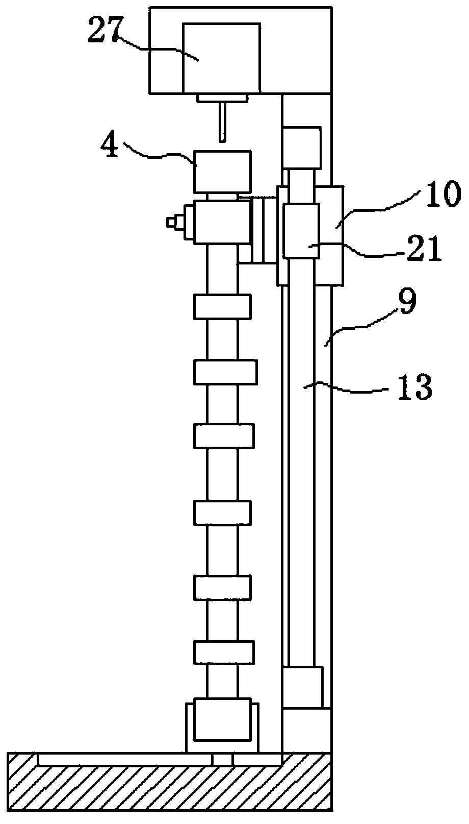
[0019] Embodiment two: if Figure 3 to Figure 6 As shown, the structure of the second embodiment is basically the same as that of the first embodiment, the difference is that the frame is also provided with a vertically extending vertical guide column 9, and the vertical guide column 9 is movably installed with The guide sleeve 10, the positioning seat 7 is fixedly installed on the guide sleeve 10, and the stud is fixedly installed on the positioning seat 7. In this embodiment, the vertical guide column can double as the frame.

[0020] The bottom plate 23 of the positioning sleeve 5 is provided with a guide block movably installed in the guide groove 3, the guide block includes a left block 14 and a right block 15, and the bottom plate of the positioning sleeve is provided with a guide block along the The strip guide hole 16 that the widthwise direction of guide groove extends, described left block 14 and the right block 15 that can move along described strip guide hole are ...


PUM


Abstract

The invention discloses a camshaft drilling device. The camshaft drilling device comprises a rack, wherein a base is fixedly installed at the lower end of the rack, a guide groove which extends transversely or longitudinally is formed in the upper surface of the base, a positioning sleeve which sleeves the lower end of the cam shaft is movably installed in the guide groove, and the inner peripheral surface of the positioning sleeve is close to the outer peripheral surface of a camshaft and is in clearance fit with the lower end of the camshaft; a cam shaft positioning device located above thepositioning sleeve is further arranged on the rack, and a drilling device which is positioned above the upper end of the cam shaft is further arranged on the rack; the camshaft positioning device is located above the positioning sleeve to fix the camshaft and the rack together, the lower end of the cam shaft is inserted into the positioning sleeve, the positioning sleeve can move along the guide groove, the position of the positioning sleeve can be adjusted relative to the guide groove so that free movement of the lower end of the cam shaft can be limited; and meanwhile, positioning interference is avoided.

Description

technical field [0001] The invention relates to a camshaft drilling device. Background technique [0002] The production and processing of camshafts requires high precision. In the prior art, the center hole of the camshaft is processed by the claw plate on the lathe to fix the journal of the camshaft, the rotation of the main shaft drives the camshaft to rotate, and the fixed drill bit is fed to the end face of the camshaft to realize the machining of the center hole, but this The processing method only ensures the fixation of one side of the camshaft, but cannot guarantee the levelness of the center hole, which will easily cause the error amplification of the subsequent processing process, and the clamping and positioning operation is complicated, which has a great impact on the processing efficiency. Contents of the invention [0003] In order to make up for the above deficiencies, the present invention provides a camshaft drilling device which can effectively improve ...

Claims


Application Information

Patent Timeline
Patent Type & Authority Applications(China)
IPC IPC(8): B23B41/00B23Q3/06
Inventor 王刚
Owner SHENGRUI TRANSMISSION
Why Eureka
Try Eureka