Electric lamp

A technology for electric lamps and lamp houses, applied to discharge lamps, gas discharge lamps, circuits, etc., can solve problems such as troublesome cutting operations, pollution, and reduced mechanical strength

Inactive Publication Date: 2005-07-13
KONINKLIJKE PHILIPS ELECTRONICS NV
View PDF1 Cites 1 Cited by
  • Summary
  • Abstract
  • Description
  • Claims
  • Application Information

AI Technical Summary

Problems solved by technology

But the cutting operation is not only troublesome, but also causes pollution
In addition, due to the arrangement of the grooves, the electrical conductivity and the mechanical strength of the outer current conductor of the known lamp are reduced

Method used


Image

  • Electric lamp
  • Electric lamp
  • Electric lamp

Examples


Embodiment Construction

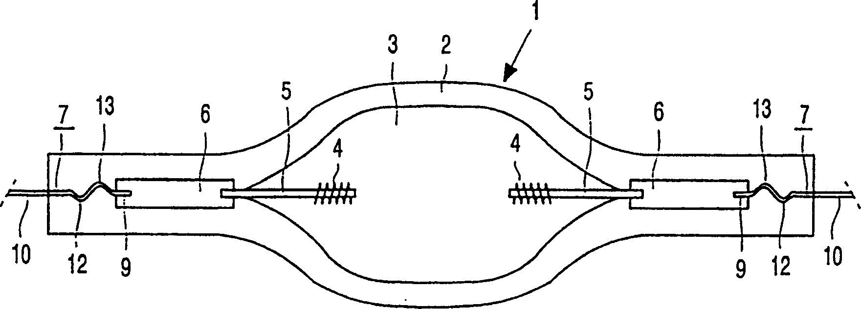
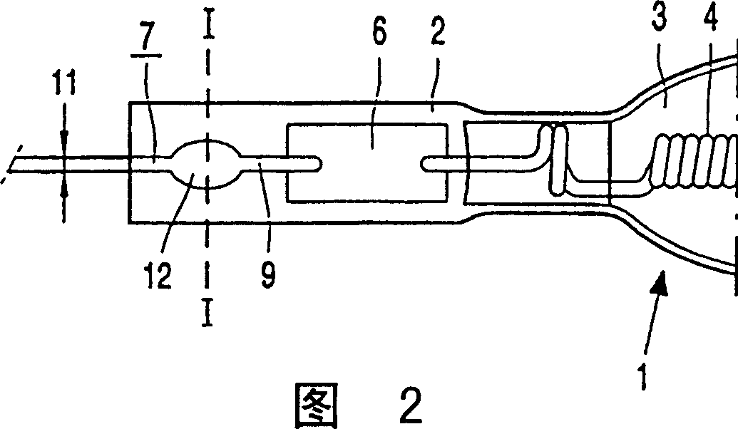
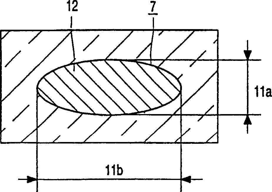
[0015] figure 1 The electric lamp in is a high-pressure gas discharge lamp having a lamp vessel 1 sealed in a vacuum-tight manner and a quartz glass wall 2 of an enclosed space 3 . The electrical element 4, that is, a pair of electrodes 4 in the figure is connected to a corresponding metal foil 6 through a respective inner current conductor 5, and the inner current conductor 5 extends from the wall 2 of the lamp chamber 1 into the space 3. The metal foil 6 is composed of molybdenum containing 0.5% by weight of diyttrium trioxide. figure 1 The middle metal foil 6 is embedded in the wall 2 of the lamp vessel 1 and is connected, ie welded in the figure, to an outer current conductor 7 made of molybdenum. Each outer current conductor 7 connected to a respective metal foil 6 comprises a first end 9 and a second end 10 . The inner current conductor 5 and the electrical element 4 are made of tungsten and may contain minor additions to adjust the grain growth of tungsten, such as 0....


PUM


Abstract

An electric lamp, comprising: a light-permeable lamp chamber (1) sealed in a vacuum-tight manner, a space (3) for accommodating an electric element (4) sealed by a quartz glass wall (2), the electric element (4 ) is connected to a metal foil (6) completely embedded in the wall (2) via an inner current conductor (5) protruding from the wall (2) of the lamp vessel (1) into the space (3); and at least one outer current conductor (7) having a first end (9), a second end (10) and a diameter (11), said first end (9) being connected to the metal foil (6) and completely sealed in the lamp housing (1) In the wall (2), said second end (10) protrudes from the wall (2) to the outside; the fixed part includes the first end ( 9) Deformation region, characterized in that the deformation region of the fixing part comprises a bending region (12) at the first end (9), so that the lifetime of the current feed of the lamp is increased in terms of resistance to mechanical loads.

Description

technical field [0001] The invention relates to an electric lamp comprising a vacuum-tight light-permeable lamp chamber, sealed by quartz glass walls to a space containing electrical components which are completely sealed to each other by an inner current conductor protruding from the wall into the space. foil connections in the walls; and [0002] at least one outer current conductor having a first end connected to the metal foil and being completely sealed within the wall of the lamp vessel, a second end protruding from the wall to the outside and a diameter of ; [0003] The fixed portion includes a deformable area at the first end of the outer current conductor cooperating with the sealing wall. Background technique [0004] A lamp of this type is described in DE-C-1016848. During the manufacture of such a lamp, for sealing, one or more of said outer current conductors are partially inserted into the wall. In the sealing zone, the quartz glass is softened at the conn...

Claims


Application Information

Patent Timeline
Patent Type & Authority Patents(China)
IPC IPC(8): H01J61/36
CPCH01J61/36H01J61/366
Inventor R·菲德尔W·M·奥勒施
Owner KONINKLIJKE PHILIPS ELECTRONICS NV
Why Eureka
Try Eureka