
Method of steady state non-decoupling for multiphase coupling power transmission line

A transmission line, non-decoupling technology, applied in the steady-state non-decoupling field, can solve the problems of heavy workload, low efficiency, poor adaptability, etc.

Inactive Publication Date: 2008-06-18
南方电网技术研究中心 +1
View PDF0 Cites 6 Cited by
  • Summary
  • Abstract
  • Description
  • Claims
  • Application Information

AI Technical Summary

Problems solved by technology

The disadvantages of these two methods are poor adaptability, cumbersome calculation, large workload and low efficiency.

Method used


Image

  • Method of steady state non-decoupling for multiphase coupling power transmission line
  • Method of steady state non-decoupling for multiphase coupling power transmission line
  • Method of steady state non-decoupling for multiphase coupling power transmission line

Examples


Embodiment

[0051] The invention is used in a steady-state non-decoupling method for multi-phase coupled transmission lines, which directly converts the multi-phase coupled transmission lines into a node analysis model-node admittance matrix under phase coordinates.

[0052] The establishment method of the above node analysis model is as follows:

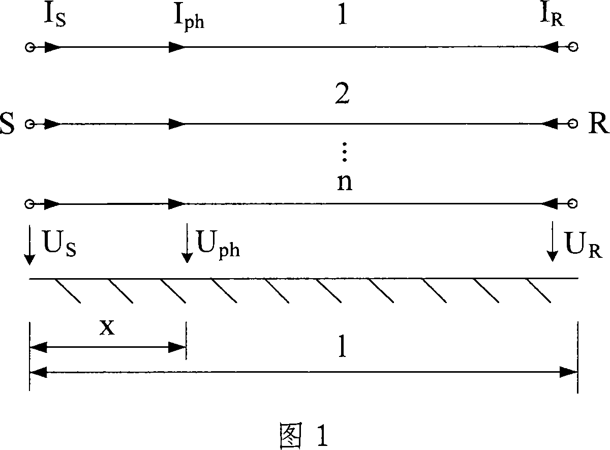
[0053] Assume that the n-phase transmission line considered is shown in Figure 1. in, with are the n-dimensional column vectors composed of the sending end, the receiving end and the phase currents at the distance x from the sending end;  S ,  R and  ph are the n-dimensional column vectors composed of the relative ground voltages at the sending end, the receiving end, and the distance x from the sending end, respectively. The frequency domain equation describing the characteristics of a polyphase transmission line is:

[0054] - d U . ...


PUM


Abstract

The invention provides a steady non-decoupling method used for multiphase coupling transmission lines. The invention directly converts the multiphase coupling transmission line into a node analysis model-node admittance matrix under a phase coordinate. By adopting the matrix differential equation theory, the invention directly derives the node analysis model-node admittance matrix of the multiphase coupling transmission line under the phase coordinate, and gives a direct algorithm which calculates the node admittance matrix. The algorithm does not diagonalize the matrix that Gamma is equal to (ZY) <1 / 2>, thus avoiding the trouble brought by adopting a phase-module conversion method. The non-decoupling method of the multiphase coupling transmission line of the invention is a steady non-decoupling method which is used for multiphase coupling transmission line and has the advantages of wide adaptability, being directly applied to the electric network analyse, greatly reducing calculation quantity and high efficiency.

Description

Technical field: [0001] The invention is a steady-state non-decoupling method for multiphase coupling transmission lines, which belongs to the innovative technology of the decoupling method for multiphase coupling transmission lines. Background technique: [0002] Transmission lines are the most basic and most numerous components in power systems. How to effectively simulate transmission lines is an important part of power system calculations. In the past, when the phase coordinate method was used to calculate the power system, two models were often used for the simulation of multi-phase coupled transmission lines: one is the conventional matrix π model which is similar to the conventional π model of single-phase transmission lines without considering the effect of distributed parameters; Another model is the exact matrix π model that takes into account the effects of distribution parameters. The disadvantages of these two methods are poor adaptability, cumbersome calculati...

Claims


Application Information

Patent Timeline
IPC IPC(8): H02J3/00
Inventor 黎小林徐政黄莹
Owner 南方电网技术研究中心
Learn More