Imaging apparatus and exposal control method for the same

A camera device and exposure control technology, which is applied in image communication, color TV parts, TV system parts, etc., can solve the problem that the face cannot be exposed, and achieve the effect of suppressing the influence of brightness

Active Publication Date: 2008-06-18
RICOH KK
View PDF1 Cites 38 Cited by
  • Summary
  • Abstract
  • Description
  • Claims
  • Application Information

AI Technical Summary

Problems solved by technology

[0007] However, in the past, in the rectangular photometry area set on the face, since the part near the right angle of the rectangle is located outside the face, when the outside of the face, that is, the peripheral background part of the face has a large difference in brightness compared with the face, When the difference is different, due to the influence of the background brightness around the face, the face may not be properly exposed

Method used


Image

  • Imaging apparatus and exposal control method for the same
  • Imaging apparatus and exposal control method for the same
  • Imaging apparatus and exposal control method for the same

Examples


Embodiment 1

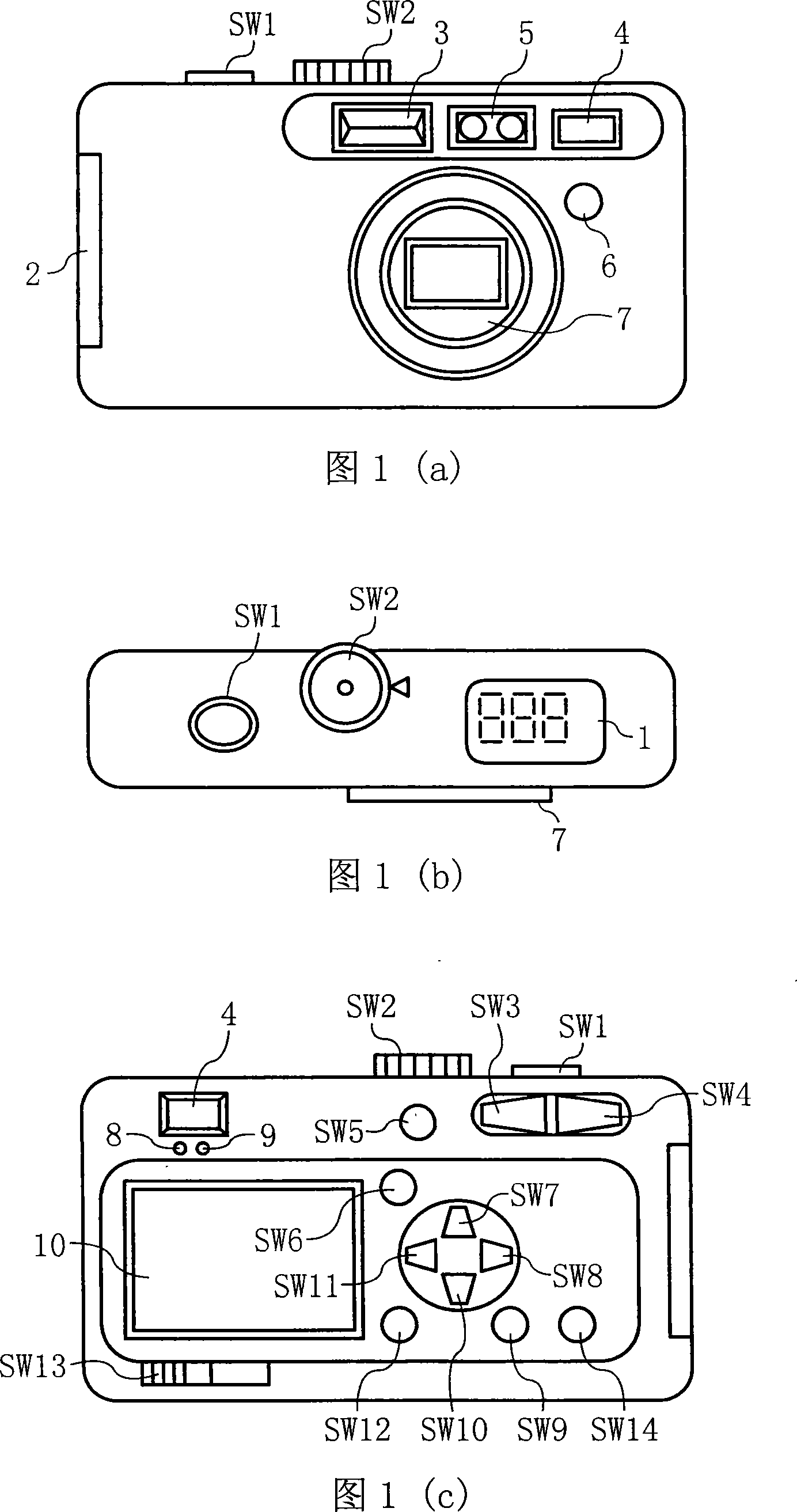
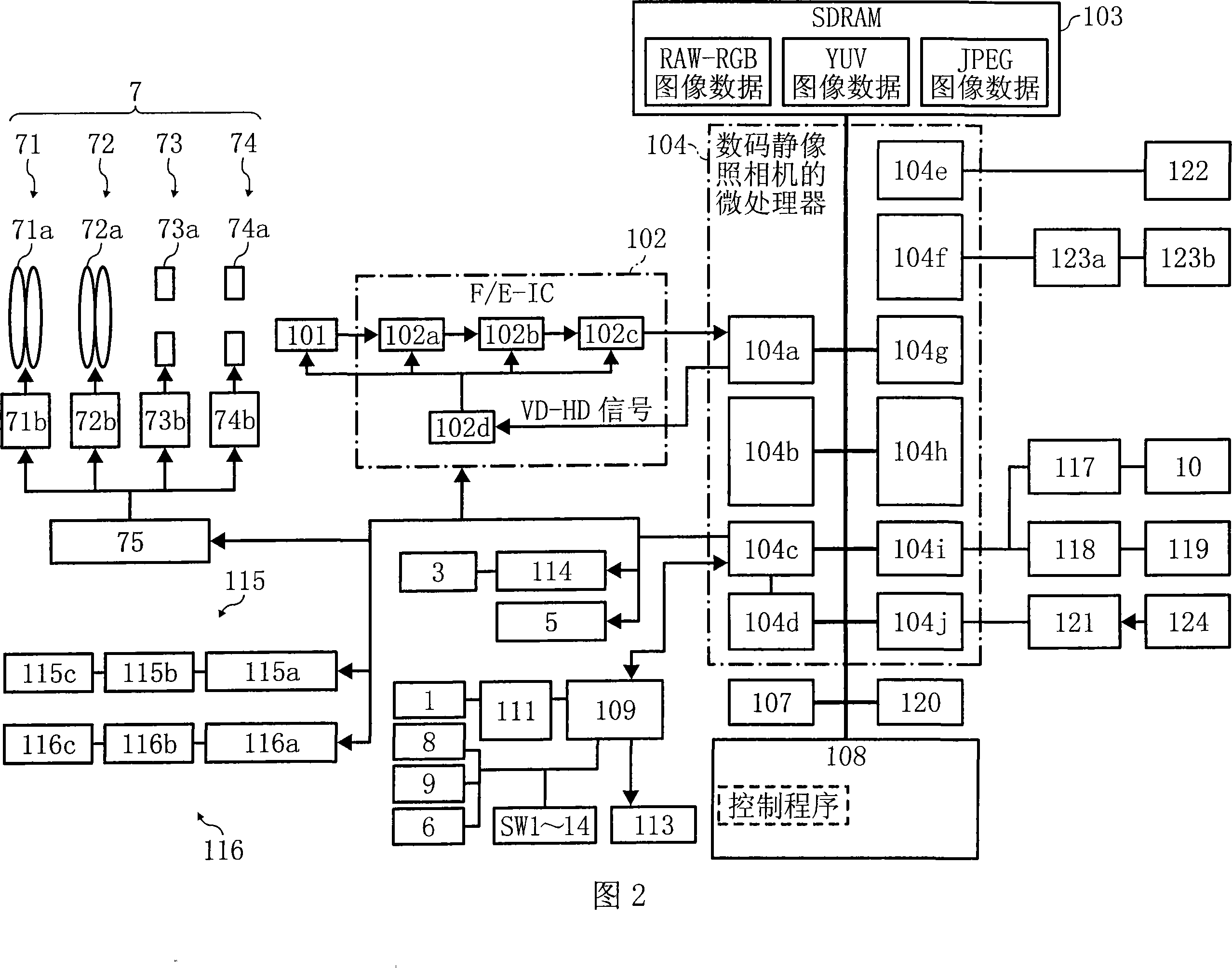
[0081] Fig. 1 (a) is a front view of an imaging device related to Embodiment 1 of the present invention, i.e. a digital still camera (hereinafter referred to as a digital camera), Fig. 1 (b) is a top view thereof, and Fig. 1 (c) is a front view thereof Rear view, Fig. 2 is a schematic block diagram showing the internal system structure of the digital camera shown in Fig. 1(a), (b), and (c).

[0082] (Appearance structure of a digital camera)

[0083] 1(a), (b), and (c), the upper part of the digital camera according to Embodiment 1 of the present invention is equipped with a shutter release button SW1, a mode dial SW2, and a secondary LCD display, that is, a secondary liquid crystal display 1. On the front of the digital camera, that is, on the side of the subject, there are a flash light emitting unit 3, an optical viewfinder 4, a distance measuring unit 5, a remote control light receiving unit 6, and a lens barrel unit 7 including a plurality of optical systems.

[0084] On...

Embodiment 2

[0139] The above-mentioned embodiment 1 is concerned with the appropriate exposure for the face and body parts of the subject person in the picture, but in this embodiment, in addition to the face and body part of the subject person, other areas in the picture are also taken into consideration , that takes into account the entire frame.

[0140] The digital camera in this embodiment has the same structure as the digital camera shown in FIGS. 1 and 2 .

[0141] Next, with reference to the flow chart shown in FIG. 9 , how to control the exposure in this embodiment to obtain proper exposure for the face and body parts of the subject and other parts of the area, that is, the entire screen, will be described.

[0142] The processing of S1 to S7 in this embodiment is the same as that of Embodiment 1 shown in FIG. 5 , and thus the description of the processing of S1 to S7 is omitted.

[0143] In S7, after the photometry processing is performed on the person's body part as the photom...

Embodiment 3

[0149] In the face detection operation mode of this embodiment, when a person's face is detected in the subject image, and the photometry area is set for the detected person's face, the area range is reduced so that the photometry area is located at the person's face. within the face. The structure of the digital camera in this embodiment is the same as that of the digital camera shown in FIG. 1 and FIG. 2 . In addition, in this embodiment, the CPU module 104c has the functions of the face detection unit, the exposure control unit, the photometry area setting unit, and the photometry unit described in the above-mentioned summary of the present invention.

[0150] Next, how to perform exposure control in this embodiment will be described with reference to the flowchart shown in FIG. 10 .

[0151] After the photographer half-presses the release shutter SW1 to turn on the AE operation (S21), the CPU module 104c of the microprocessor 104 judges whether the mode dial SW2 is set to...


PUM


Abstract

The present invention provides an imaging device capable of appropriately exposing the face and the body of a subject person at the same time. This imaging device is provided with: CCD101, is used for inputting the image data corresponding to the subject; The human face detection unit that is implemented by CPU module 104c in the digital camera microprocessor 104, is used in the picture that the image data that CCD101 outputs obtains. Detect people's faces; the first light metering unit implemented by the CPU module 104c measures the people's faces detected by the CPU module 104c as the light metering area; the second light metering unit implemented by the CPU module 104c judges the detected people In the upper and lower direction of the face, the part below the face is used as the photometering area for photometry; the exposure control unit implemented by the CPU module 104c calculates the exposure according to the photometry results of the first photometry unit and the photometry results of the second unit, and then Exposure control is performed based on the calculated exposure amount.

Description

technical field [0001] The present invention relates to an imaging device such as a digital camera having an automatic exposure function and an exposure control method for the imaging device. Background technique [0002] In the previous exposure decision-making methods of digital still cameras, the following methods are well known: multi-zone weighted metering method, which divides the metering range in the screen into multiple metering areas, and the results obtained from each metering area The metering result determines the exposure method; the center-weighted metering method, which places the metering focus on the center of the screen for metering; the central part metering method, which only measures the center of the screen, which accounts for more than ten percent of the screen. Spot metering, this method measures the light at the center of the screen about a few percent of the range, and so on. [0003] However, in the above-mentioned...

Claims


Application Information

Patent Timeline
Patent Type & Authority Applications(China)
IPC IPC(8): H04N5/235G06K9/00
Inventor 杉浦康一山田学
Owner RICOH KK
Why Eureka
Try Eureka