Imaging apparatus and exposal control method for the same
A camera device and exposure control technology, which is applied in image communication, color TV parts, TV system parts, etc., can solve the problem that the face cannot be exposed, achieve the suppression of the influence of brightness, and high-precision exposure control Effect
- Summary
- Abstract
- Description
- Claims
- Application Information
AI Technical Summary
Problems solved by technology
Method used
Image
Examples
Embodiment 1
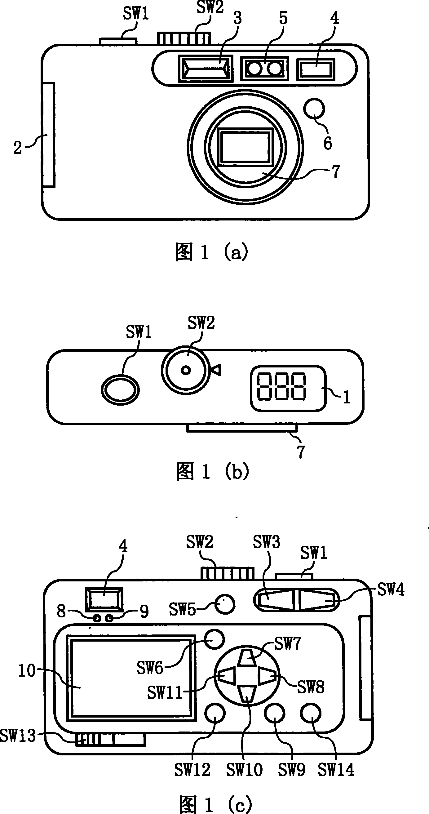
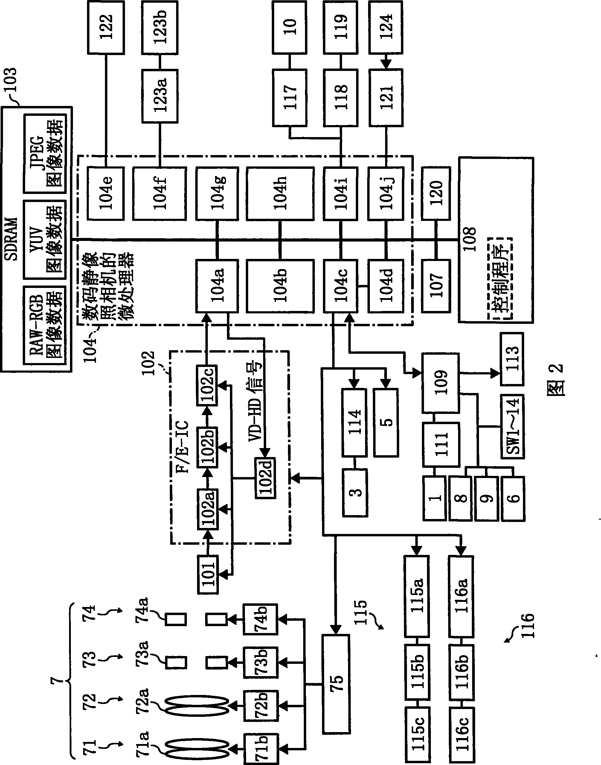
[0078] Fig. 1 (a) is a front view of an imaging device related to Embodiment 1 of the present invention, i.e. a digital still camera (hereinafter referred to as a digital camera), Fig. 1 (b) is a top view thereof, and Fig. 1 (c) is a front view thereof Rear view, figure 2 It is a schematic block diagram showing the internal system structure of the digital camera shown in Fig. 1 (a), (b) and (c).
[0079] (Appearance structure of a digital camera)
[0080] 1(a), (b), and (c), the upper part of the digital camera according to Embodiment 1 of the present invention is equipped with a shutter release button SW1, a mode dial SW2, and a secondary LCD display, that is, a secondary liquid crystal display 1. On the front of the digital camera, that is, on the side of the subject, there are a flash light emitting unit 3, an optical viewfinder 4, a distance measuring unit 5, a remote control light receiving unit 6, and a lens barrel unit 7 including a plurality of optical systems.
[00...
Embodiment 2
[0136] The above-mentioned embodiment 1 is concerned with the appropriate exposure for the face and body parts of the subject person in the picture, but in this embodiment, in addition to the face and body part of the subject person, other areas in the picture are also taken into consideration , that takes into account the entire frame.
[0137] The digital camera in this embodiment has the same figure 2 The digital camera shown is the same structure.
[0138] Below, refer to Figure 9 The flow chart shown in this embodiment describes how to control the exposure so that the face and body parts of the subject person and other parts of the area, that is, the entire picture, obtain proper exposure.
[0139] The processing of S1 to S7 in the present embodiment is the same as Figure 5 The illustrated embodiment 1 is the same, and thus the explanation about the processing of S1 to S7 is omitted.
[0140] In S7, after the photometry processing is performed on the person's body p...
Embodiment 3
[0146] In the face detection operation mode of this embodiment, when a person's face is detected in the subject image, and the photometry area is set for the detected person's face, the area range is reduced so that the photometry area is located at the person's face. within the face. The structure of the digital camera in the present embodiment is the same as that of Fig. 1, figure 2 The digital still cameras shown have the same structure. In addition, in this embodiment, the CPU module 104c has the functions of the face detection unit, the exposure control unit, the photometry area setting unit, and the photometry unit described in the above-mentioned summary of the present invention.
[0147] Below, refer to Figure 10 The flow chart shown illustrates how exposure control is performed in this embodiment.
[0148] After the photographer half-presses the release shutter SW1 to turn on the AE operation (S21), the CPU module 104c of the microprocessor 104 judges whether the ...
PUM
 Abstract
Description
Claims
Application Information
 - R&D
- Intellectual Property
- Life Sciences
- Materials
- Tech Scout
- Unparalleled Data Quality
- Higher Quality Content
- 60% Fewer Hallucinations
Browse by: Latest US Patents, China's latest patents, Technical Efficacy Thesaurus, Application Domain, Technology Topic, Popular Technical Reports.
© 2025 PatSnap. All rights reserved.Legal|Privacy policy|Modern Slavery Act Transparency Statement|Sitemap|About US| Contact US: help@patsnap.com


