
Pipeline optimizer system

A pipeline system, genetic optimization technology, applied in the field of pipeline optimizer system

Active Publication Date: 2008-06-18
LAIR LIQUIDE SA POUR LETUDE & LEXPLOITATION DES PROCEDES GEORGES CLAUDE
View PDF0 Cites 10 Cited by
  • Summary
  • Abstract
  • Description
  • Claims
  • Application Information

AI Technical Summary

Problems solved by technology

This often leads to suboptimal solutions
Additionally, even when current systems have been shown to determine high-quality solutions, they often fail to do so in a reasonable amount of time

Method used


Image

  • Pipeline optimizer system
  • Pipeline optimizer system
  • Pipeline optimizer system

Examples


Embodiment Construction

[0022] Embodiments of the present invention provide a computerized optimization system that can be used to optimize various aspects of pipeline operations. Generally, the term "optimization" is used herein to describe a change in the operational state of a pipeline over another—usually in terms of power or other operating costs. Embodiments of the present invention provide an optimization system that can be used to determine low-cost solutions to problems that satisfy pipeline operating constraints. It should be noted, however, that embodiments of the present invention do not require determining the best or best solution for the piping configuration. In contrast, the term "optimization" generally refers to finding an acceptable solution to a difficult problem in a reasonable amount of time.

[0023] In one embodiment, the optimization system is an application software configured to find high-quality solutions to optimization problems. In the case of piping systems, the optim...


PUM


Abstract

One embodiment of the invention provides a method for optimizing a variety of aspects of pipeline operations by using a genetic algorithm. Generally, the genetic algorithm is used to evolve a population of feasible solutions over successive generations until a termination condition is satisfied. Each solution specifies a feasible operational state of the pipeline system. Over successive generations existing solutions are modified, and an identified solution in the population is removed at each successive generation. Over repeated generations, the solutions in the population improve. Once an optimized production solution is generated, an optimized pressure solution may be generated using a direct pressure optimization process.

Description

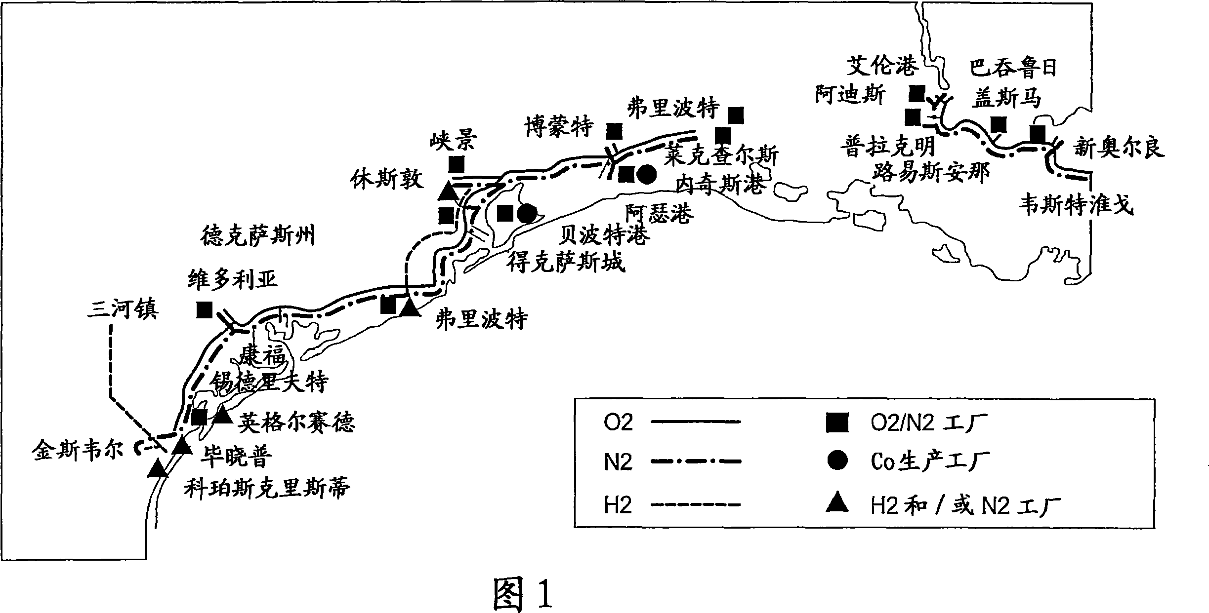
Background technique [0001] Typically, a piping system consists of a continuous line of pipes and also includes equipment such as valves, compressor stations, communication systems and metering devices used to transport liquid or gaseous substances from one point to another, usually from a production or processing point to another production or processing point, or point of use. For example, FIG. 1 shows a dual conduit system that also includes a gaseous nitrogen conduit running parallel to the gaseous oxygen conduit. Plants are shown at various locations along the pipeline route where air separation units, compressors, boosters, regulators and other plant elements operate to introduce material into the pipeline. [0002] Optimizing the operation / running of a piping system such as the one shown in Figure 1 is a complex undertaking. In particular, it has been demonstrated that optimizing piping systems to take into account power costs at each node, reconfigurable elements (e....

Claims


Application Information

Patent Timeline
IPC IPC(8): G06N3/12G06Q10/00F17D3/00G06Q10/04
CPCF17D3/00G06N3/126G06F9/38G06F9/455G06G7/48G06N3/12
Inventor C·N·哈珀M·T·博措
Owner LAIR LIQUIDE SA POUR LETUDE & LEXPLOITATION DES PROCEDES GEORGES CLAUDE
Learn More