
Printing press with printing plate manipulation device

A printing machine and printing device technology, applied in printing machines, rotary printing machines, printing, etc., can solve the problems of paper moisture and easy deformation of texture, and achieve the effect of overcoming geometric structure deviation

Inactive Publication Date: 2008-06-25
HEIDELBERGER DRUCKMASCHINEN AG
View PDF2 Cites 10 Cited by
  • Summary
  • Abstract
  • Description
  • Claims
  • Application Information

AI Technical Summary

Problems solved by technology

[0004] However, the problem often arises during the printing process that the geometry of the printed image tends to deform due to the wetness and texture of the paper

Method used


Image

  • Printing press with printing plate manipulation device
  • Printing press with printing plate manipulation device
  • Printing press with printing plate manipulation device

Examples


Embodiment Construction

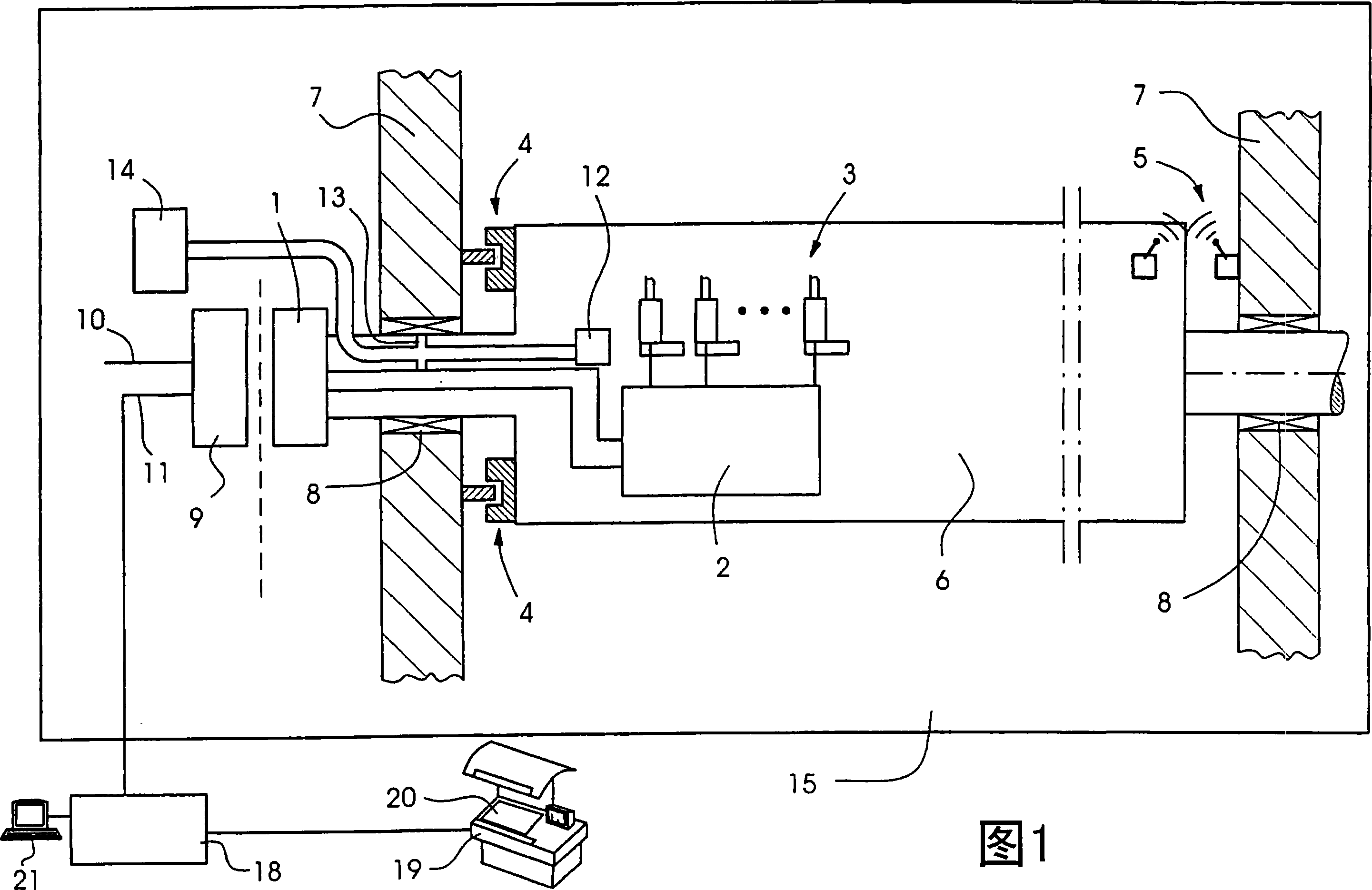
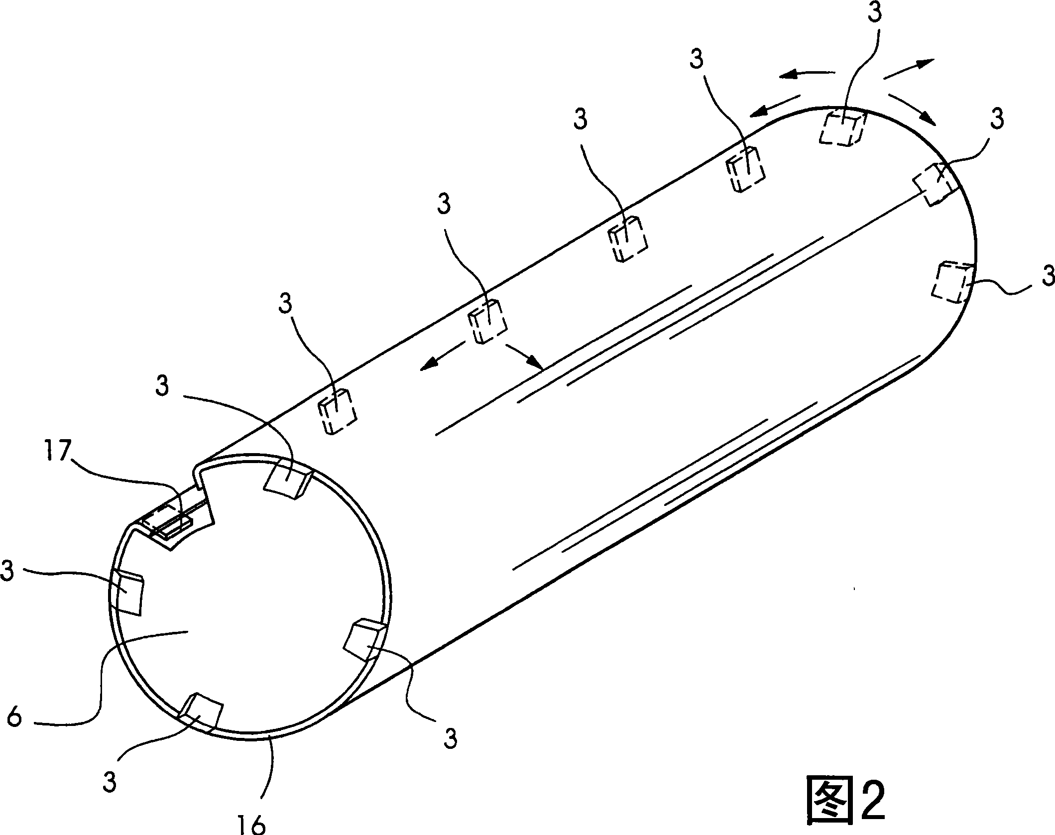
[0025] A part of a printing unit of a sheet-fed printing press 15 is schematically shown in FIG. 1 . This part includes the plate cylinder 6 , the lateral supports 8 and a part of the control of the actuator 3 . The plate cylinder 6 is mounted rotatably on both sides in corresponding side walls 7 of the printing press 15 . A plurality of actuators 3 are arranged on the plate cylinder 6, said actuators 3 each engaging (angereifen) on the outer edge of a printing plate located on the plate cylinder 6, which is shown in detail in FIG. 2 . Through the movement of these actuators 3 , the printing plates 16 located on the plate cylinder 6 can be deformed not only in the circumferential direction but also in the axial direction. The deformation of the printing plate 16 simultaneously changes the printing image on the printing plate 16 accordingly. The actuators 3 are operated as electric motors in FIG. 1 , which are connected to a positioning electronics unit 2 . The positioning ...


PUM


Abstract

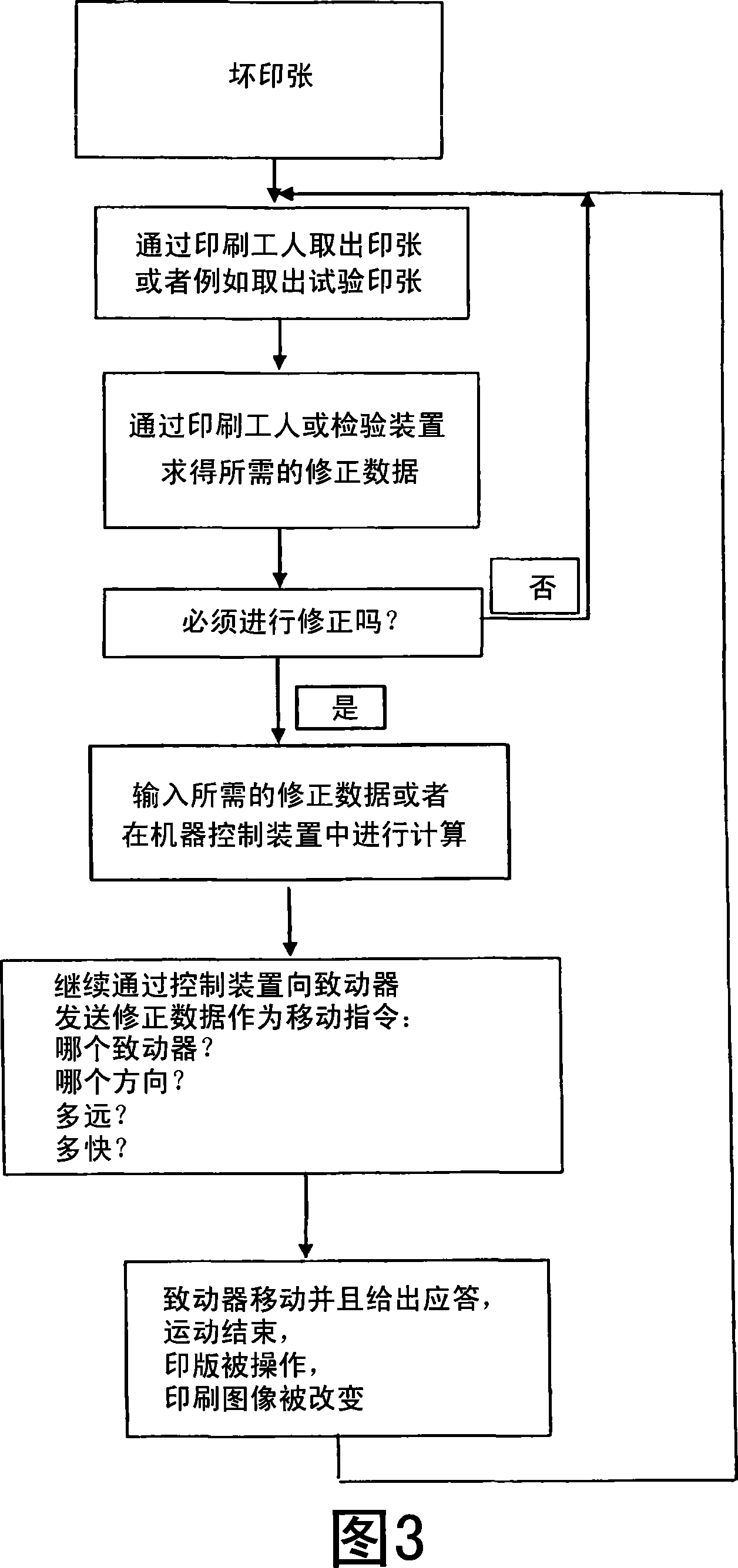
A printing press includes at least one printing unit having a cylinder and a cover covering the cylinder. Actuators are associated with the cylinder for changing a geometry of the cover in axial and / or circumferential direction of the cylinder. Positioning electronics are connected to the actuators and a printing press machine control system is connected to the positioning electronics. An image inspection device is connected to the printing press machine control system at least for geometric measurement of printed printing materials. A printing press computer processes measured results from the image inspection device for carrying out a desired / actual value comparison and for driving the actuators to minimize determined deviations, in the event that deviations are determined.

Description

technical field [0001] The invention relates to a printing press having at least one printing unit with a covered cylinder. Background technique [0002] In rotary sheet-fed printing presses, the plate cylinders and blanket cylinders in the individual printing units of the printing press are provided with clamping and tensioning devices which allow blankets and printing formes to be changed. In each new printing job, therefore, a new printing forme can be tensioned onto the associated cylinder in the respective printing unit. According to the prior art, the printing plate is fastened to the plate cylinder by means of hydraulic or pneumatic tensioning and clamping devices. Such a clamping device for fastening a printing plate on a cylinder in a printing unit of a printing press is known from DE 4129831 C3. In this case, the printing forme is fixed on the printing cylinder by means of a fixed upper clamping plate and a lower clamping plate which is radially displaceable rela...

Claims


Application Information

Patent Timeline
Patent Type & Authority Applications(China)
IPC IPC(8): B41F13/16B41F33/08
CPCB41F33/0036B41P2227/40B41F27/005
Inventor K·许格尔R·施特尔贝格尔K·阿尔布雷希特P·海勒尔K-D·克莱鲍姆许特M·克拉斯尼奇M·克吕格尔J·孔茨B·马斯J·马斯G·默克尔H·迈尔
Owner HEIDELBERGER DRUCKMASCHINEN AG
Learn More