Piston with oil collector ring

An oil collecting ring and piston technology, applied in the direction of piston, piston ring, cylindrical piston, etc., can solve the problems of affecting the distribution of lubricating oil, inappropriate, etc., and achieve the effect of full sealing effect

Inactive Publication Date: 2008-06-25
WAERTSILAE SCHWEIZ AG
View PDF5 Cites 14 Cited by
  • Summary
  • Abstract
  • Description
  • Claims
  • Application Information

AI Technical Summary

Problems solved by technology

[0028] Even if the important central problem detailed above could be solved by this solution, the use of the techniques described in this patent would only inappropriately or inconsequentially affect the distribution of lubricating oil that has been applied to the running surfaces of the cylinder

Method used


Image

  • Piston with oil collector ring
  • Piston with oil collector ring
  • Piston with oil collector ring

Examples


Embodiment Construction

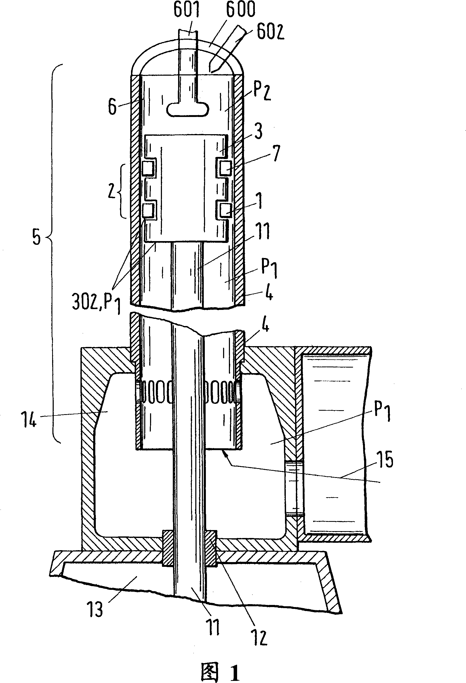
[0093] Figure 1 shows a schematic illustration of a cylinder arrangement in partial section with a cylinder liner, a piston according to the invention and a fresh air supply system, wherein the piston comprises a piston ring set with an oil collector ring, the oil collector ring In the following text, it is indicated generally with the reference number 1 .

[0094] The cylinder arrangement of Fig. 1 is a typical arrangement for longitudinally scavenged large two-stroke Diesel machines known per se from the prior art.

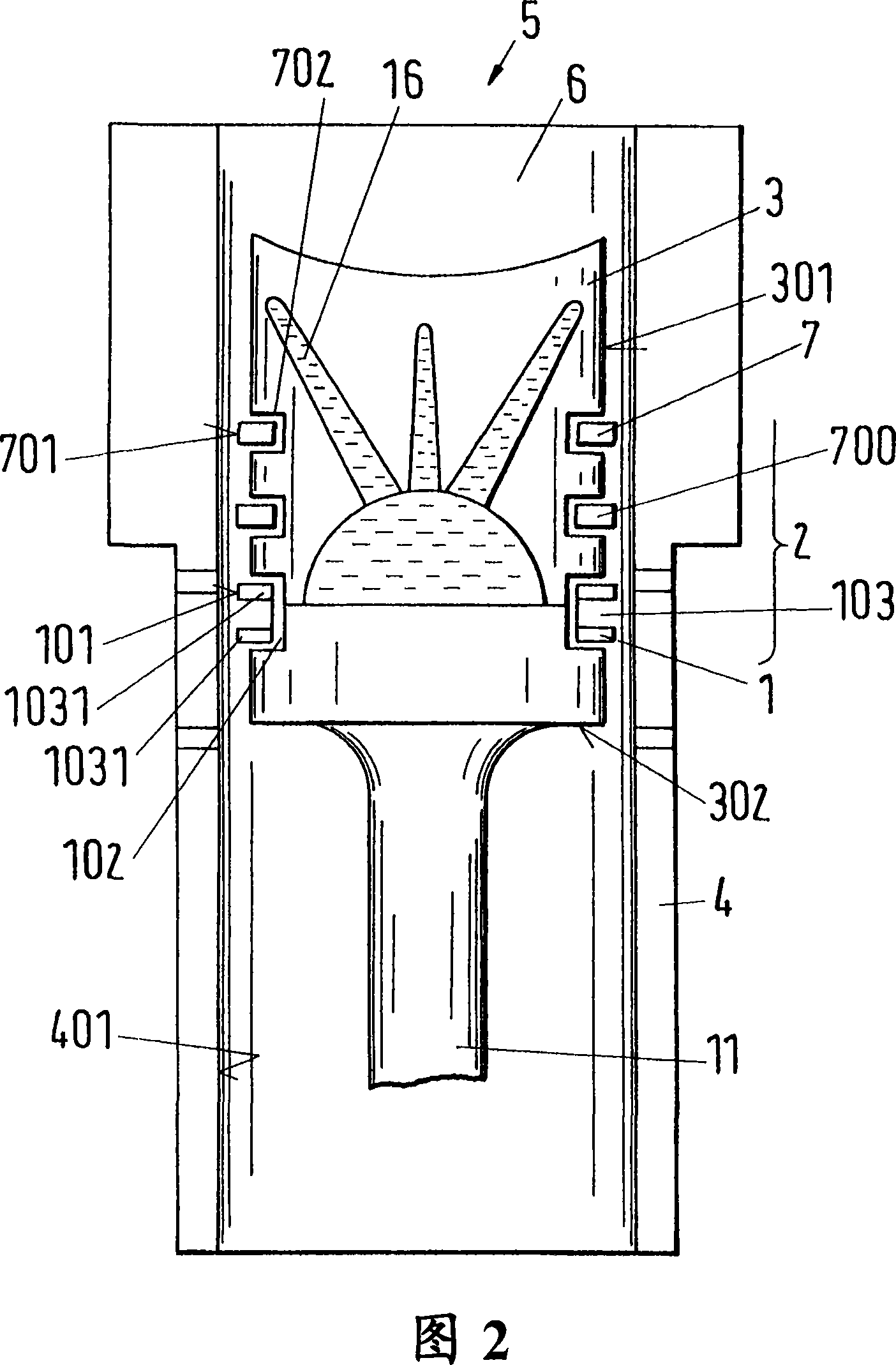
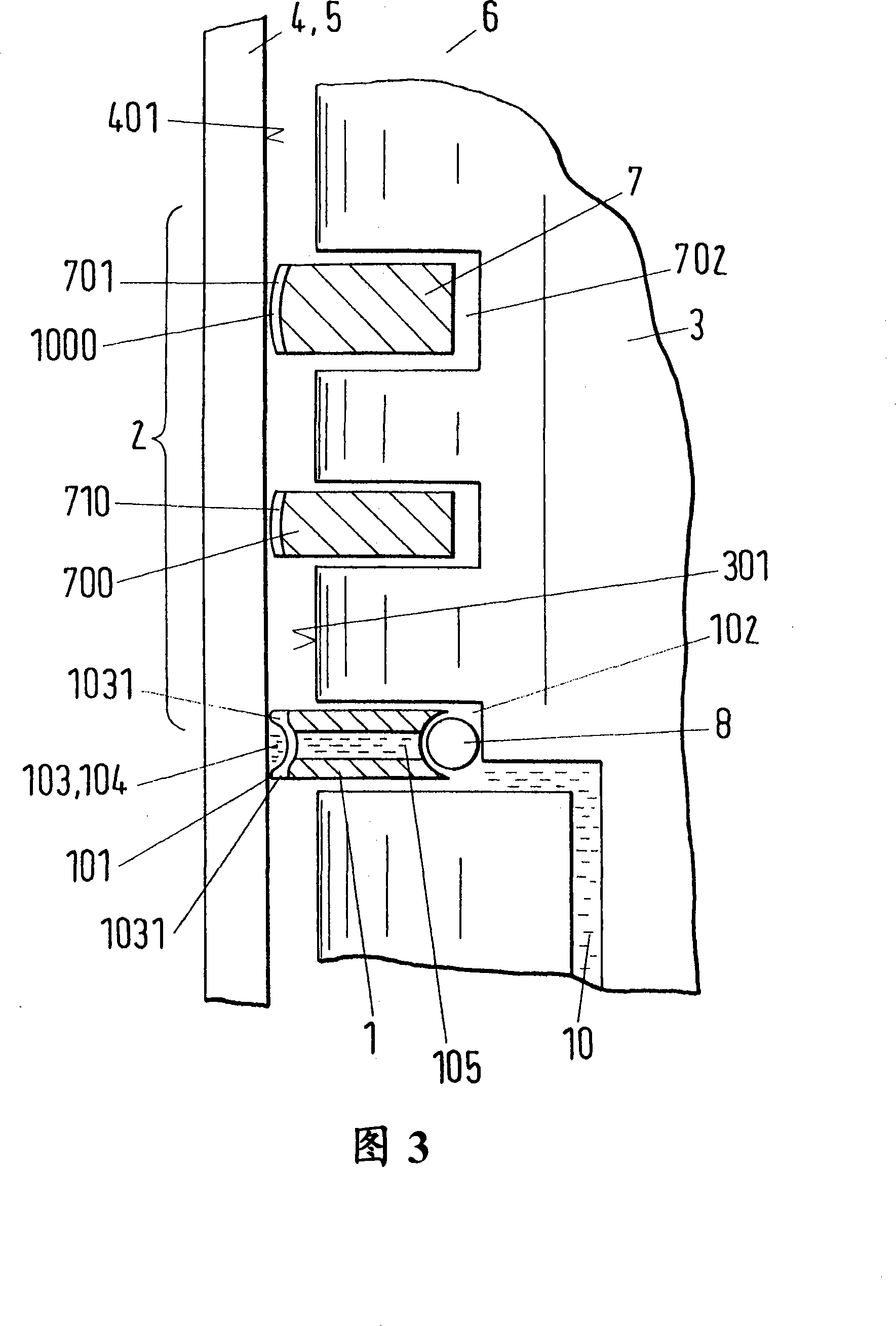
[0095] The arrangement comprises a cylinder 5 , also indicated as a cylinder liner 5 , wherein a piston 3 is arranged to be able to move back and forth along a cylinder wall 4 of the cylinder 5 . The piston 3 comprises a piston ring set 2 which is here schematically illustrated with only two piston rings, ie with a first piston ring 7 located closest to the combustion chamber 6, which is also called top ring 7 and has a first running surface 701 with which the ...


PUM


Abstract

The invention relates to a piston (3) with an oil collecting ring, the piston is used in a large two-stroke Diesel machine, the oil collecting ring (1) is used to form a piston ring group (2), and the piston is set to The installed state can move back and forth along the cylinder wall (4) of the cylinder (5) of the large-scale two-stroke diesel engine, and the piston ring group (2) includes a The first piston ring (7) of the first running surface (701) and the oil collector ring (1) with the collecting ring running surface (101), and the first piston ring (7) is set in the first piston ring groove (702 ) and the oil collecting ring (1) is set in the collecting ring groove (102) of the piston (3), so that the first running surface (701) of the first piston ring (7) and the collecting of the oil collecting ring in the operating state The ring running surface (101) is in frictional contact with the cylinder running surface (401) of the cylinder wall (4). According to the invention, the piston (3) has lubricating oil holes in the area of ​​the catch ring groove (102) and / or in the catch ring groove (102), the piston (3) being designed such that lubricating oil can flow from the piston (3) through the lubricating oil holes ) is applied to the cylinder running surface.

Description

technical field [0001] The invention relates to a piston with an oil collecting ring for forming a piston ring set for a piston of a large two-stroke internal combustion engine (combustion engine). The piston is arranged to move back and forth along the cylinder wall of the cylinder of the large two-stroke diesel engine in the installed state, the piston ring set includes a first piston with a first running surface located closest to the combustion chamber of the cylinder ring and the oil collector ring with a collector ring running surface, and the first piston ring is arranged in the first piston ring groove of the piston and the oil collector ring is arranged in the collector ring groove of the piston, so that in the operating state The first running surface of the first piston ring and the collector ring running surface of the oil collector ring are in frictional contact with the cylinder running surface of the cylinder wall. Background technique [0002] Pistons known ...

Claims


Application Information

Patent Timeline
Patent Type & Authority Applications(China)
IPC IPC(8): F02F3/10F02F5/00F16J1/01F16J9/26F16J9/28
CPCF16J9/206F02F3/00F02F5/00
Inventor K·拉斯
Owner WAERTSILAE SCHWEIZ AG
Why Eureka
Try Eureka