Weighing method of electronic belt conveyor scale capable of checking automatically

An electronic belt scale and weighing technology, which is applied in the direction of continuous material flow weighing equipment, weighing equipment testing/calibration, weighing, etc., can solve the problem of increasing the cycle and cost of purchasing components, many fault points, and failure to find out in time, etc. problems, to achieve the effect of improving reliability and stability, increasing signal transmission distance, and facilitating repair and maintenance

Active Publication Date: 2008-06-25
云南昆船电子设备有限公司
View PDF1 Cites 41 Cited by
  • Summary
  • Abstract
  • Description
  • Claims
  • Application Information

AI Technical Summary

Problems solved by technology

First of all, because the load cell outputs a voltage signal and the voltage is small (generally 0-24mv), its anti-interference ability is poor, so the signal transmission distance cannot be too long; secondly, due to the centralized conversion of the weighing output voltage signals of all sensors As an analog signal, the entire weighing device has only one weighing output signal transmitted to the PLC, and it is impossible to monitor and diagnose each weighing sensor in real time
When the electronic belt scale has faults such as out-of-tolerance measurement accuracy and damage to the load cell during operation, it cannot be found in time; third, when the electronic belt scale is found to have faults such as out-of-tolerance measurement accuracy and damage to the load cell It is difficult to find the fault point in a short time, and we can only find it bit by bit from the mechanical system and weighing system based on experience. There are many fault points that can be judged, and the maintenance is difficult and takes a long time; Fourth, due to the adoption of The hardware balance bridge needs to match the characteristic parameters of 2 or

Method used


Image

  • Weighing method of electronic belt conveyor scale capable of checking automatically

Examples


Embodiment Construction

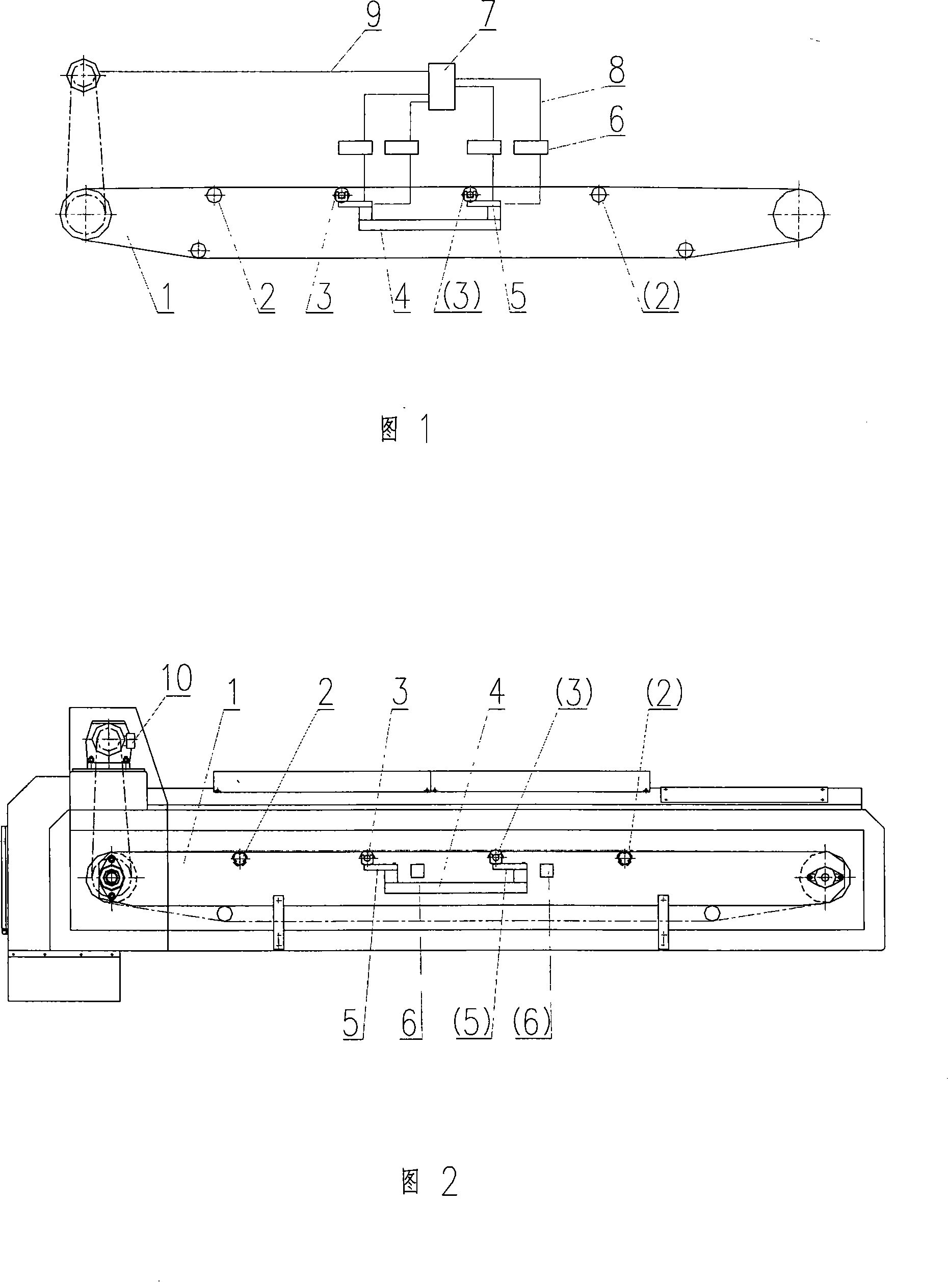
[0016] As shown in Figure 1, the present invention forms the weighing device 4 of electronic belt scale with two or more weighing rollers 3, and each weighing roller is supported by two or more load cells 5. When the load cell is a digital sensor, each load cell is connected to the PLC 7 through its own signal transmission line 8 . When the load cell is an analog sensor, an analog transmitter or a digital transmitter 6 is set on the weight signal transmission line 8 connecting each analog sensor to the PLC, and the weighing output signal of each load cell is simulated The transmitter independently performs voltage / current conversion, amplification, and filtering and then transmits to the PLC, or the digital transmitter independently performs amplification, filtering, and A / D conversion and then transmits to the PLC. The PLC directly obtains the weighing value of each load cell. Output signals for real-time monitoring and diagnosis of weighing devices. A transmission line 9 fo...


PUM


Abstract

The invention relates to a weighing method for an electronic belt scale capable of self-check, more than two weighing carrier rollers (3) form into a weighing device of the electronic belt scale, each weighing carrier roller is supported by more than two weighing sensors (5), each weighting sensor is respectively connected with a PLC (7) through an individual signal transmission line (8), the PLC can directly acquire an output weighing signal of each weighing sensor to monitor and diagnose each weighing carrier roller and weighing sensor on real-time in the weighing process. During a normal weighing, the method measures according to a multiple carrier roller mode. The PLC monitors, recognizes, diagnoses, groups and compares the weight signals after A/D transition on real-time, and calculates the material weight after integral arithmetic with speed signals of a motor or the belt. During thediagnosis, the weighing device treat according to more than two single carrier roller manners, and each weighing carrier roller is measuring cup for each other. The invention has strong ability of disturbance resistance, and can find out failures such as poor measuring accuracy, damaged weighing sensor, etc., the performance is stable and reliable, the failure point can be quickly checked out so as to be maintained conveniently, the maintenance capacity and component replacement quantity are in a small quantity.

Description

technical field [0001] The invention relates to the technical field of electronic belt scales, and mainly relates to a weighing method capable of accurate weighing and convenient fault detection. Background technique [0002] At present, the electronic belt scales produced at home and abroad are composed of a belt conveyor and a scale frame, including single roller, double roller, full suspension, direct load-bearing and other modes, and the weighing output voltage signals of all weighing sensors are generally It is all centralized input to the balance bridge, which is uniformly converted by the balance bridge to obtain an analog signal, which is then amplified, filtered, and A / D converted, and then sent to the PLC to calculate the weight of the material through calculation. First of all, because the load cell outputs a voltage signal and the voltage is small (generally 0-24mv), its anti-interference ability is poor, so the signal transmission distance cannot be too long; se...

Claims


Application Information

Patent Timeline
IPC IPC(8): G01G11/00G01G23/01
Inventor 李亚林徐信荣孔昭龙罗清敏张浩王帆白炜张磊
Owner 云南昆船电子设备有限公司
Why Eureka
Try Eureka