

Optical thin film of back light module group
An optical film and backlight module technology, applied in optics, nonlinear optics, prisms, etc., can solve the problems of reducing the life of the roller, colloid residue, and easy to have glue residue on the roller, and achieve the effect of avoiding glue residue.
- Summary
- Abstract
- Description
- Claims
- Application Information
AI Technical Summary
Problems solved by technology
Method used
Image

Examples
no. 1 example
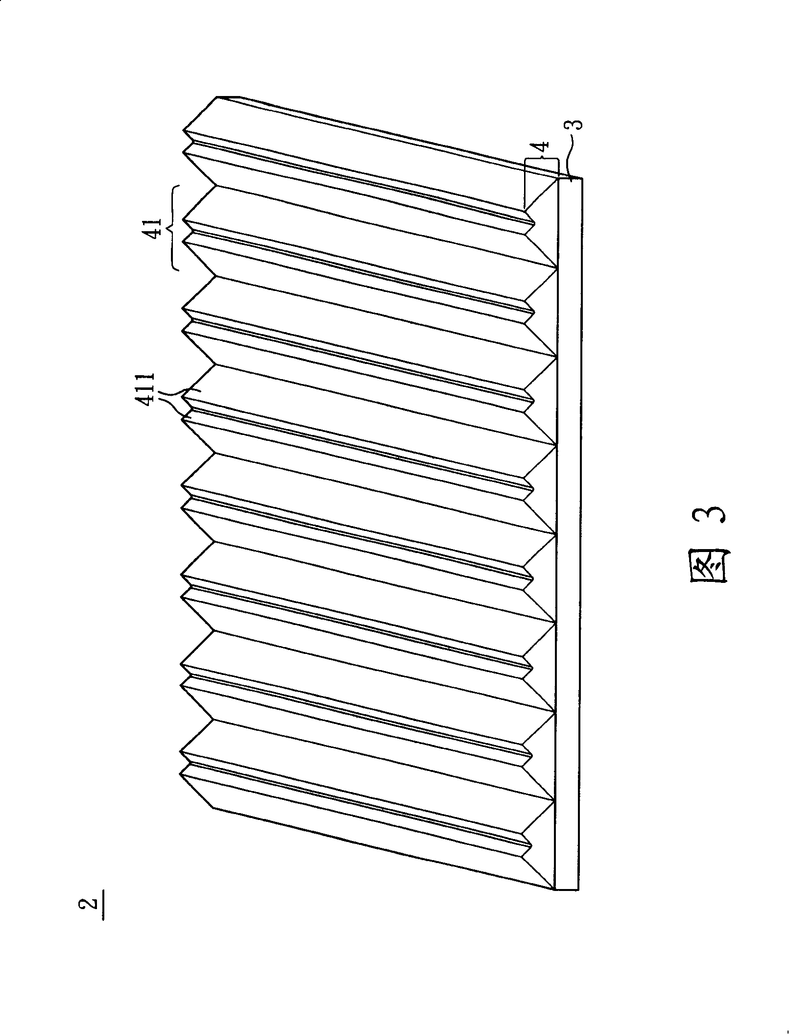
[0062] As shown in FIG. 3 , the optical film 2 of the backlight module includes a substrate 3 and a prism sheet 4 . Wherein, the material of the substrate 3 may be Poly(ethylene terephthalate), PET, and the thickness may be between 30 μm and 250 μm according to actual design requirements.
[0063] The prism sheet 4 is disposed on one side of the substrate 3 , and the prism sheet 4 can be formed by using a roller as a mold to coat the substrate 3 with photocurable glue, perform an embossing process, and then cure with ultraviolet rays. Of course, the manufacturing method of the prism sheet 4 is not limited thereto, and it can also be embossed on a mold with a light-curing glue by a roller, and then pasted on the substrate 3 after curing.
[0064] Please refer to Figure 3 and Figure 4 , where, while Figure 4 It is an enlarged schematic view of one of the prism patterns 41 in FIG. 3 . The prism sheet 4 includes a plurality of periodically arranged prism patterns 41, that is to...
no. 2 example
[0072] Please refer to Figure 9 In this embodiment, the main difference from the first embodiment is that the number of triangular prisms 411 included in each prism pattern 41 is different. Here, take the case of 2n+1 triangular prisms and n=1 as an example, which means that the prism pattern 41 has three triangular prisms as an example. The prism pattern 41 in the figure has a first prism 411a, a second prism 411b and a third prism 411c, wherein a rounded corner 412 is formed between the first prism 411a and the second prism 411b. Certainly, the fillet 412 can also be formed between the second prism 411b and the third prism 411c at the same time.
[0073] In addition, the size of the prism pattern 41 of this embodiment is also different from that of the first embodiment. Here, the period length D of the prism pattern 41 is 100 μm, the first prism 411a has a first height H1 (20 μm), and the second prism 411b Having a second height H2 (30 μm) and a third prism 411c having a ...
no. 3 example
[0076] Please refer to Figure 10 In this embodiment, the main difference from the first embodiment and the second embodiment is that the number of triangular prisms 411 included in each prism pattern 41 is different. Here, the case where there are 2n triangular prisms and n is equal to 2 is taken as an example, which means that the prism pattern 41 has four triangular prisms as an example. The prism pattern 41 in the figure has a first prism 411a, a second prism 411b, a third prism 411c and a fourth prism 411d, wherein a rounded corner 412 is formed between the second prism 411b and the third prism 411c. The position of the rounded corner 412 is not fixed, of course, the rounded corner 412 can also be formed between the first prism 411 a and the second prism 411 b or between the third prism 411 c and the fourth prism 411 d.
[0077] In addition, the size of the prism pattern 41 is also different from the above-mentioned embodiments, and here, the period length D of the prism...
PUM
| Property | Measurement | Unit |
|---|---|---|
| thickness | aaaaa | aaaaa |
| length | aaaaa | aaaaa |
| length | aaaaa | aaaaa |
Abstract
Description
Claims
Application Information