Dial indicator display device
A display device, a pointer-type technology, which is applied to the visual time indicating device, analog and digital indicating, and indicating the values of multiple variables at the same time. It can solve the problem of frequent information display positions, frequent display switching, and shortened battery life. problems, to extend the action time, reduce the number of battery replacement and charging, and prolong the battery life.
- Summary
- Abstract
- Description
- Claims
- Application Information
AI Technical Summary
Problems solved by technology
Method used
Image
Examples
no. 1 Embodiment approach
[0108] (Structure of Combined Clock)
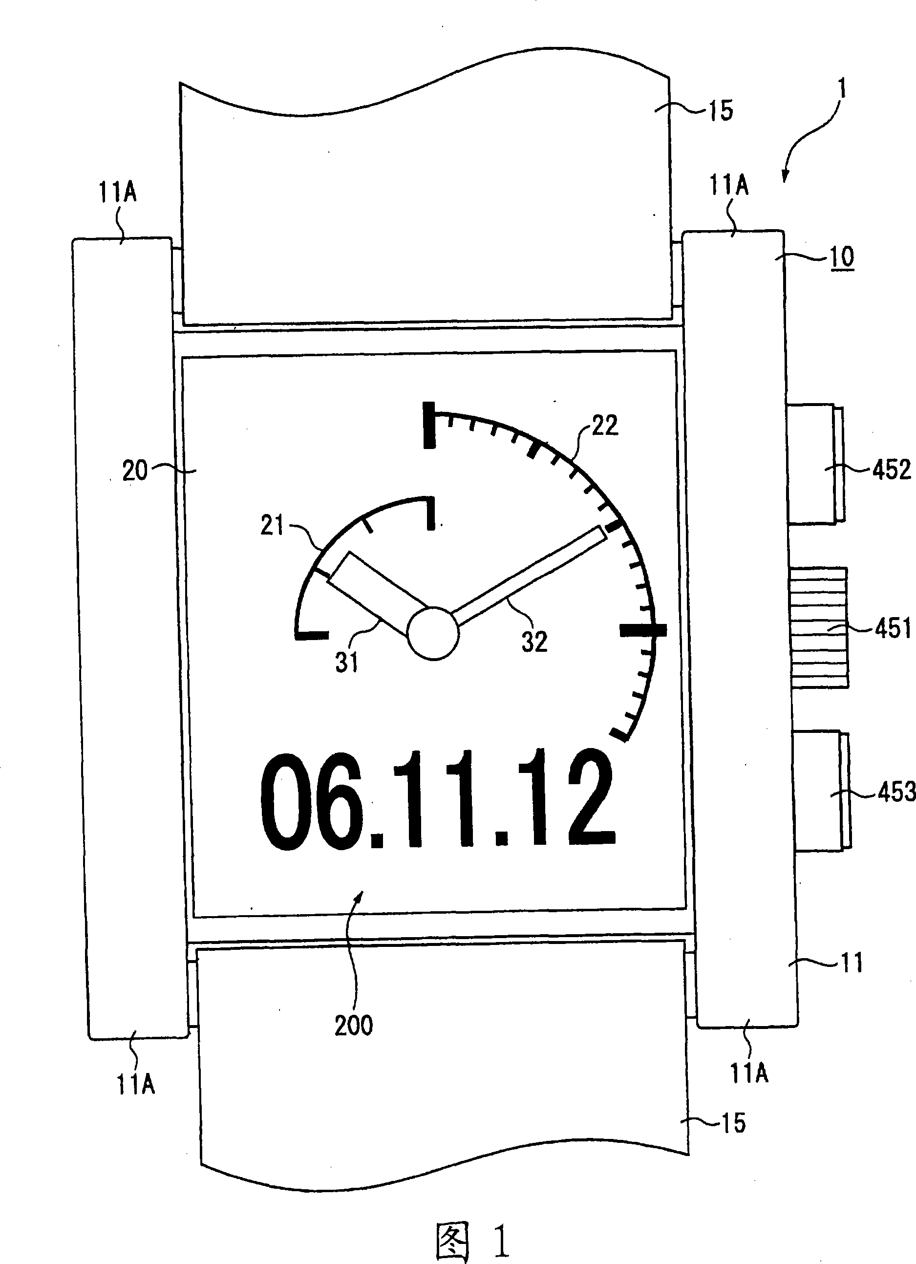
[0109] FIG. 1 is a front view of an integrated clock 1 using an analog display device according to the present invention.
[0110] Combination timepiece 1 has a timepiece body 10 and a band 15, and is a type of wristwatch worn by a user on his or her wrist.
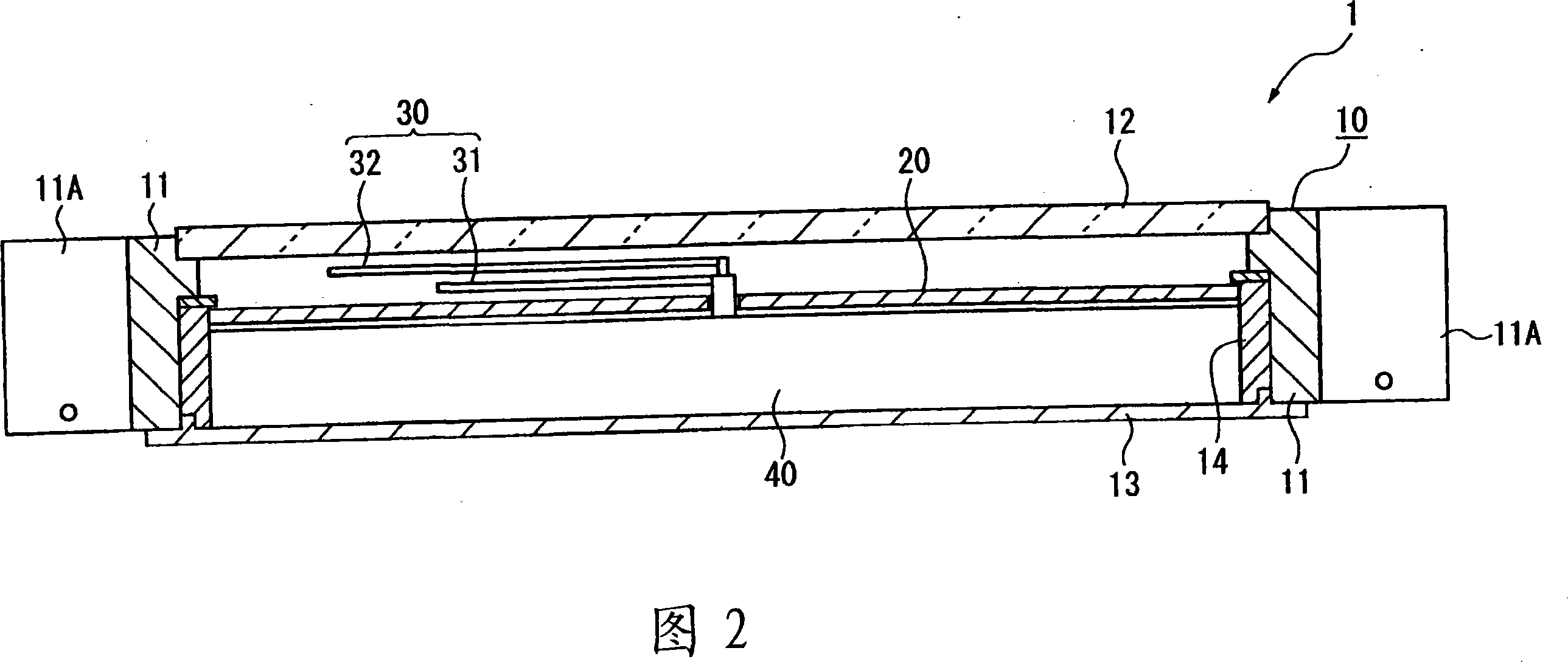
[0111] As shown in FIG. 2 , the clock main body 10 has an enclosure case (trunk) 11 formed in a substantially square cylindrical shape, a cover glass (windproof) 12 attached to the surface side of the enclosure case 11, and a cover glass (windproof) 12 detachably attached to the enclosure case. The back cover 13 on the back side of the body 11.
[0112] In addition, the packaging case 11 is not limited to being formed in a substantially square cylindrical shape (planar rectangular shape), but may be formed in a substantially cylindrical shape (planar circular shape or elliptical shape), and the shape is not limited to that shown in the illustration.
[0113] A pair of strap attachm...
no. 2 Embodiment approach
[0173] Next, a second embodiment of the present invention will be described. In addition, in each embodiment described below, the same code|symbol is attached|subjected to the same or the same structure as each said embodiment, and the description is abbreviate|omitted or abbreviate|omitted.
[0174] As shown in FIG. 6, the main difference between the combined clock 1B of the second embodiment and the combined clock 1 of the first embodiment is that a second hand 33 is additionally provided, and a scale 27 for the second hand 33 is displayed on the display panel 20, and other The structure is roughly the same. That is, the combined clock 1B is a clock that indicates "hour / minute / second" by hands.
[0175] In addition, like a normal clock, the second hand 33 is attached to and driven by a predetermined gear of the above-mentioned wheel train 47 .
[0176] However, in a normal clock, the second hand is longer than the other hour or minute hands, but the second hand 33 of this ...
no. 3 Embodiment approach
[0185] Next, a third embodiment of the present invention will be described.
[0186] As shown in FIG. 7 , in the combined clock 1C according to the third embodiment, the rotation axes of the hour hand 31 and the minute hand 32 are arranged at positions separated from the plane of the display panel 20 , not on the same axis as in the above-mentioned embodiment.
[0187] That is, the hour hand 31 is arranged on the upper left side of the display panel 20 , and the minute hand 32 is arranged on the lower right side.
[0188] The scale display control unit 414A displays four scales 21 by setting the central angle θ1 of the clock scale area 23 to 90 degrees, and displays six scales 22 by setting the central angle θ2 of the minute scale area 24 to 90 degrees. .
[0189] Information display control section 414B displays information 200 in each of the upper right and lower left areas of display panel 20 . In this embodiment, day information and world time information including city ...
PUM
 Abstract
Description
Claims
Application Information
 - R&D
- Intellectual Property
- Life Sciences
- Materials
- Tech Scout
- Unparalleled Data Quality
- Higher Quality Content
- 60% Fewer Hallucinations
Browse by: Latest US Patents, China's latest patents, Technical Efficacy Thesaurus, Application Domain, Technology Topic, Popular Technical Reports.
© 2025 PatSnap. All rights reserved.Legal|Privacy policy|Modern Slavery Act Transparency Statement|Sitemap|About US| Contact US: help@patsnap.com


