CD ROM exhaustion mechanism

A technology of optical drives and drive parts, applied in the field of optical drive fixing mechanisms, can solve problems such as difficulty in assembly and disassembly, difficulty in controlling manufacturing precision, and space constraints, and achieve the effects of easy assembly and disassembly, easy manufacturing accuracy, and improved design flexibility

Inactive Publication Date: 2008-06-25
SUZHOU JIAOZI INFORMATION TECH CO LTD
View PDF1 Cites 8 Cited by
  • Summary
  • Abstract
  • Description
  • Claims
  • Application Information

AI Technical Summary

Problems solved by technology

[0010] However, when applying the aforementioned prior art, many components need to be designed to cooperate with each other so that the optical drive can be inserted into the accommodating space of the bracket or withdrawn from the bracket from the front to the rear, and in order to avoid tools for loading and unloading, the applied components have complicated Structure
Therefore, this prior art will result in increased manufacturing costs, which is not conducive to widespread use, and it is difficult to control the manufacturing accuracy
At the same time, although China Taiwan Patent Certificate No. 292140 New Patent proposes that the elastic element such as a torsion spring can be omitted, when the elastic element is omitted, the connecting rod located in the bracket must be manually operated; however, in the electronic product The operation of the connecting rod is not only limited in space, but also requires a considerable amount of force, which also makes the operation relatively more difficult
Therefore, this prior art relatively increases the degree of difficulty of assembly and disassembly, and is inconvenient to use

Method used


Image

  • CD ROM exhaustion mechanism
  • CD ROM exhaustion mechanism
  • CD ROM exhaustion mechanism

Examples


Embodiment Construction

[0053] Embodiments of the present invention are described below through specific examples, and those skilled in the art can easily understand other advantages and effects of the present invention from the content disclosed in this specification.

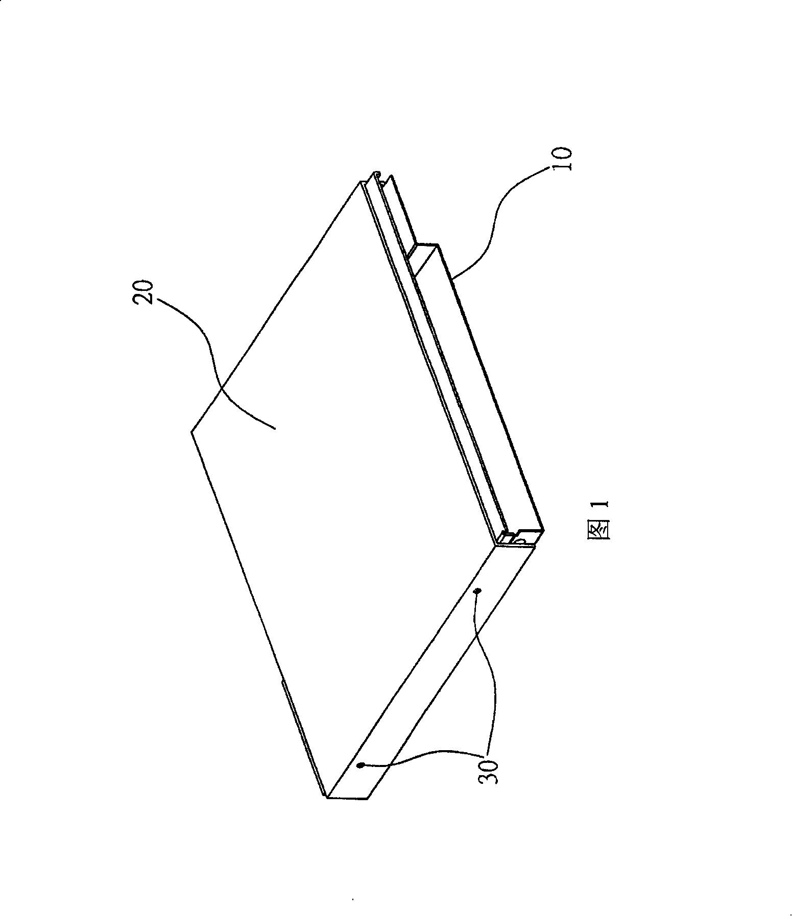
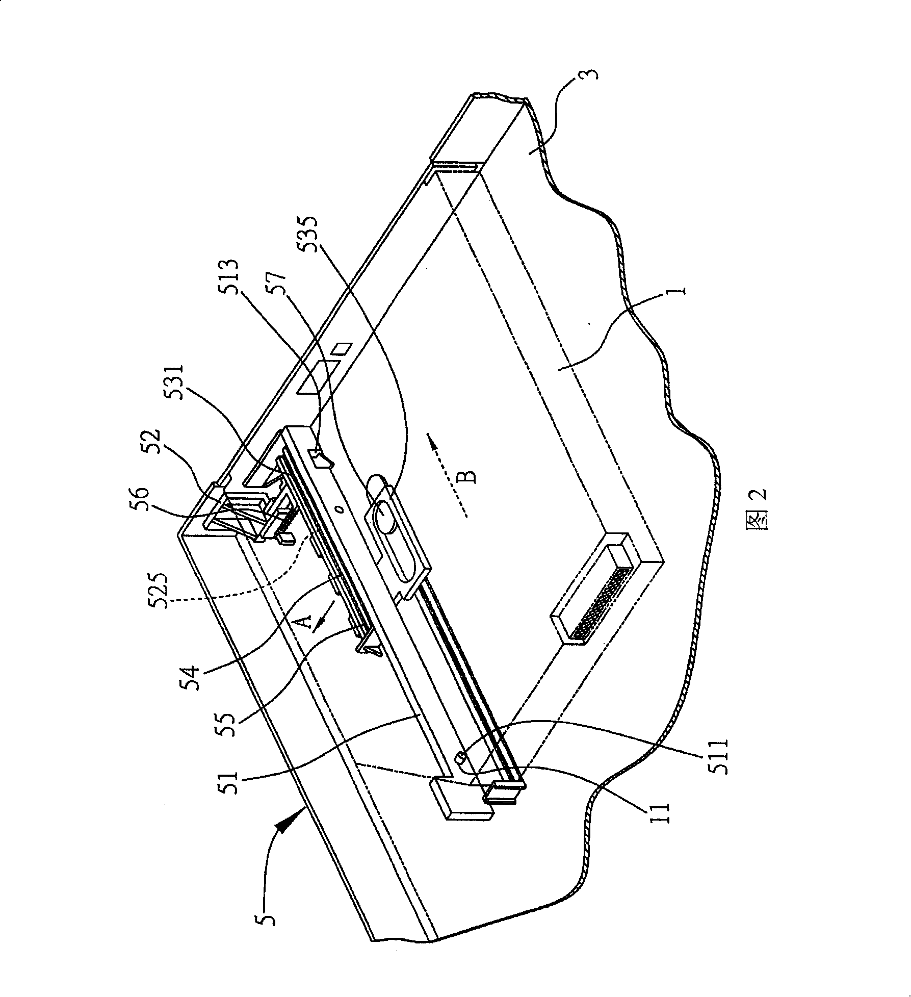
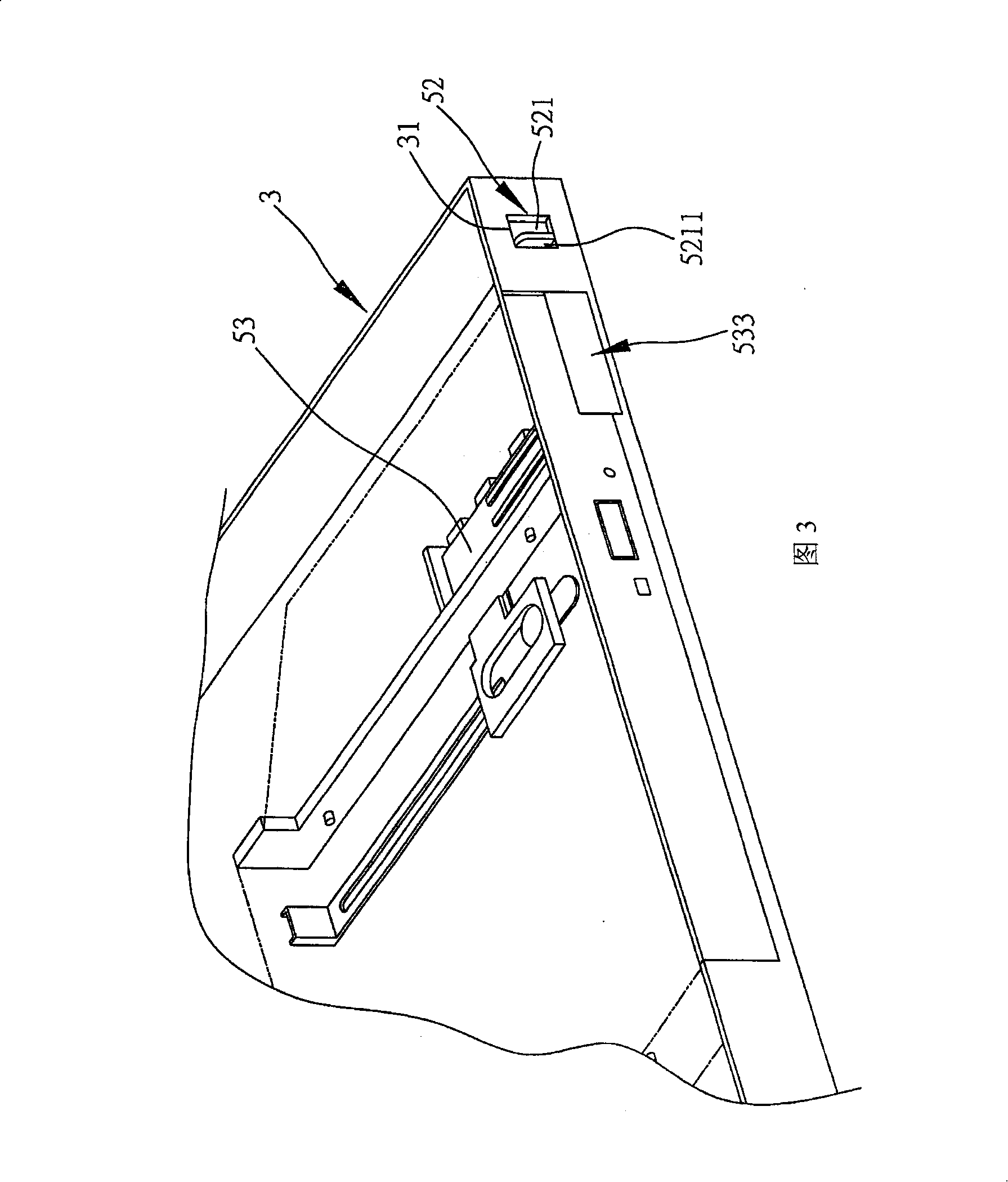
[0054]2 to 4 are schematic diagrams of preferred embodiments of the optical drive pull-out mechanism of the present invention. As shown in FIG. 2 , the present invention is applied to pull out the optical drive 1 from the bracket 3 of the electronic device. The optical drive 1 has a first coupling portion 11 disposed on the side, and the first coupling portion 11 is, for example, an opening. The optical drive pull-out mechanism 5 of the present invention includes a positioning member 51 arranged on the bracket 3 and used for correspondingly combining with the optical drive 1, a driving member 52 partially exposed on the side of the bracket 3, correspondingly combining with the driving member 52 and having a first A guide part 535 con...


PUM


Abstract

The invention discloses a CD driver pulling out mechanism, which is used for pulling out the CD driver with a first bonding part from the bracket of the electronic device. The invention comprises a positioning element arranged on the bracket and used for being correspondingly combined with the CD driver, a driving element partially exposed out of the side surface of the bracket, a motion element correspondingly combined with the driving element and is provided with a first guiding part connecting with the CD driver, a first elastic part arranged on the bottom surface of the motion element, a third position limiting part arranged on the bottom surface of the bracket, a second elastic part arranged on the bottom surface of the bracket in a free moving way, a second guiding part used for mutually moving with the first guiding part, the driving element can be turned from the side surface of the bracket, thus to cause the CD driver to be devoiced from the bracket.

Description

technical field [0001] The invention relates to a fixing technology, in particular to an optical drive fixing mechanism for fixing the optical drive in an electronic device. Background technique [0002] With the continuous development and improvement of electronic technology, the design of electronic product components is moving towards the common goal of high performance and low cost. Therefore, in electronic products, any improvement, as long as it helps to simplify the structure, facilitate assembly, reduce manufacturing costs and other substantial effects, is an invention with industrial utility value, and also conforms to the requirements of the patent law for encouragement, protection and utilization. The spirit of invention. [0003] At present, the fixed technology for installing optical disk drives (Optical Disk Drive, ODD) such as CD-R, CD-RW, DVD-RD, VD-RW, DVD+RW, etc. in electronic devices, for example, there is Chinese Taiwan Patent No. 584256 Model patents,...

Claims


Application Information

Patent Timeline
Patent Type & Authority Applications(China)
IPC IPC(8): G11B33/00G11B33/02G06F1/16
Inventor 杨永吉姜秋月
Owner SUZHOU JIAOZI INFORMATION TECH CO LTD
Why Eureka
Try Eureka