
Method and system for transmitting real time flow media based on video frequency frame splitting

A technology of media transmission and video frame, applied in the direction of digital video signal modification, television, data exchange through path configuration, etc. It can solve the problems of increasing server load, slow bandwidth fluctuation adjustment speed, etc., and achieve the goal of improving transmission speed and reducing load. Effect

Active Publication Date: 2008-06-25
ZHEJIANG UNIV OF TECH
View PDF0 Cites 24 Cited by
  • Summary
  • Abstract
  • Description
  • Claims
  • Application Information

AI Technical Summary

Problems solved by technology

However, multi-bit rate compression doubles the load on the server, and the video transmission is still carried out according to the time period, and the adjustment speed to the bandwidth fluctuation is slow

Method used


Image

  • Method and system for transmitting real time flow media based on video frequency frame splitting
  • Method and system for transmitting real time flow media based on video frequency frame splitting

Examples


Embodiment 1

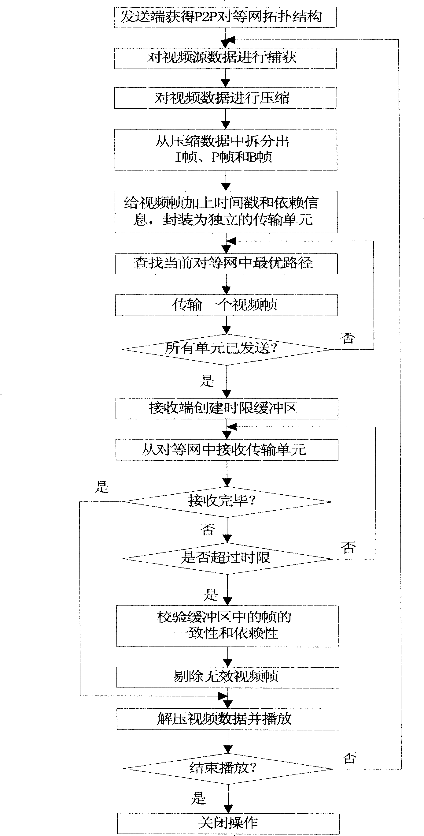
[0046] see figure 1 : a kind of real-time streaming media transmission method based on video frame splitting, comprises the following steps:

[0047] (1) Control the streaming media server to detect the topology of the entire P2P peer-to-peer network, and obtain the information of all receiving end nodes in the peer-to-peer network, including Internet addresses, available ports, upstream bandwidth, and downstream bandwidth;

[0048] (2) Capture raw video data and compress:

[0049] The sending end captures the original video bitmap data within the set time period, and then compresses the video data;

[0050] (3) Split the video frame and encapsulate the network transmission unit:

[0051] (3.1) split out I frame, B frame or P frame from video data;

[0052] (3.2) numbering each split video frame sequentially, and adding a timestamp and a frame type sign;

[0053] (3.2) Encapsulate each video frame, its number, timestamp and frame type sign;

[0054] I frame is a video frame...

Embodiment 2

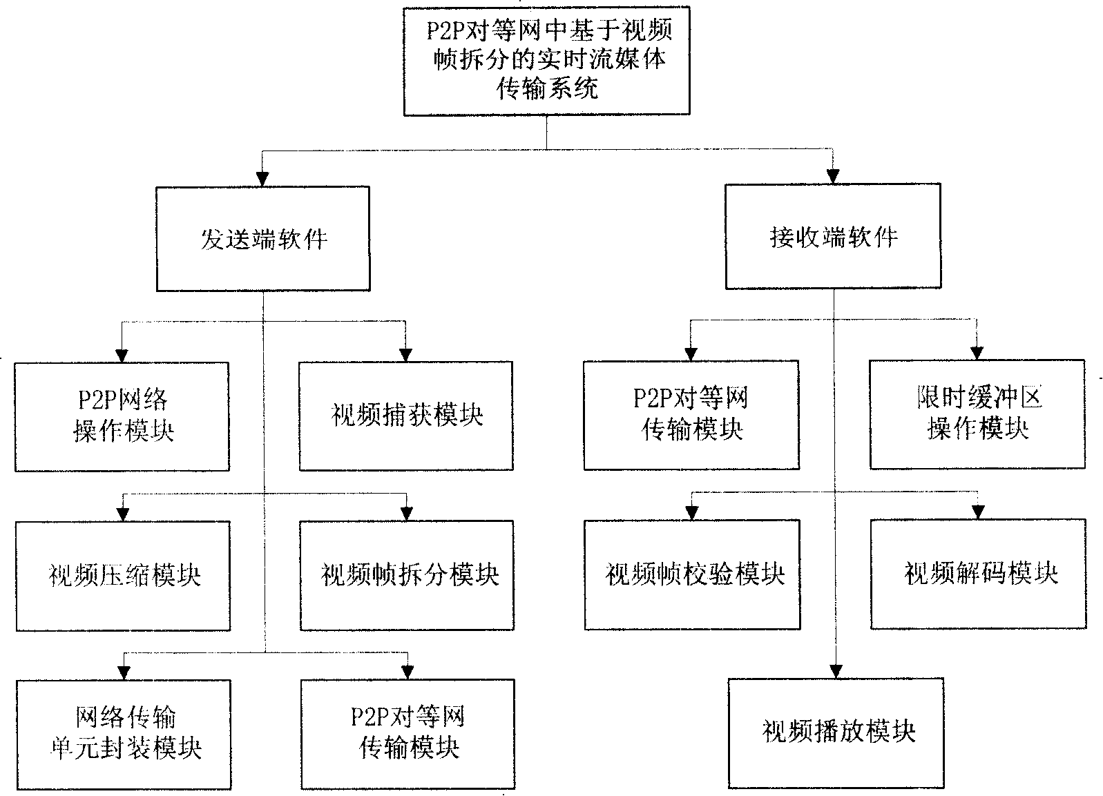
[0083] see figure 2 : A real-time streaming media transmission system based on video frame splitting, mainly including: a sending end and a receiving end:

[0084] The sender includes:

[0085] P2P network operation module: used to obtain the information of all receiving end nodes in the peer-to-peer network, and calculate the information of all receiving end nodes, and obtain the optimal transmission path;

[0086] Video capture module: used to capture the original image of the video from an external video capture device;

[0087] Video compression module: used to call the video compression algorithm as needed to compress the original video data;

[0088] Video frame splitting module: split each compressed video frame from the compressed video data;

[0089] Network transmission unit encapsulation module: used to encapsulate each video frame, its number, time stamp and frame type flag as a transmission unit in the P2P structure;

[0090] P2P peer-to-peer network transmis...


PUM


Abstract

A real-time stream media transmission method based on the video frame split includes the following steps: (1) the stream media server is controlled to explore the whole topological structure of the P2P equivalent internet and gain the whole information of receiver nodes in the equivalent internet; (2) the original video data is captured and compressed; (3) each split video frame is numbered in sequence, and a time-stamp and frame type mark is add to package; (4) the video frame is transmitted; (5) a receiver creates a time-limited buffer area to receive the video frame and saves the video frame in the buffer area in the sequence of the time-stamp; (6) the video frame in the time-limited buffer area is verified and adjusted; (7) the receiver decompresses and plays. And a system is formed by a real-time media transmission method. The invention can support a plurality of video compression method and make a fine particle size split on the base of video compression frame level, the video frame after splitting transmits independently in the topological structure of the P2P equivalent internet, and the video frame rate can be adjusted dynamically in net-speed.

Description

(1) Technical field [0001] The invention relates to a streaming media transmission method and system based on video frame splitting in a P2P peer-to-peer network. (2) Background technology [0002] P2P is the abbreviation of "peer-to-peer", and P2P can also be understood as the meaning of "peer-to-peer", or called a peer-to-peer network. From the perspective of network transmission, point-to-point is a transmission mode, and traditional transmission methods include broadcast and multicast. The concept of peer-to-peer network means that in the network topology, there are many devices and network hosts. As long as the data transmission from a single network host to other single network hosts is called point-to-point, it is different from the specific implementation software, protocols and methods. irrelevant. [0003] P2P technology is a technology used to directly exchange data or services between different PC users without going through server equipment. It breaks the tra...

Claims


Application Information

Patent Timeline
IPC IPC(8): H04N7/26H04L12/28H04N19/184H04N19/423H04N19/46H04N19/85
Inventor 王万良蒋一波赵燕伟任敏徐新黎郑建炜
Owner ZHEJIANG UNIV OF TECH
Learn More