Permanent magnetic suspension and magnetic wheel pushing vehicle

A magnetic levitation and magnetic wheel technology, which is applied to electric vehicles, vehicle parts, railway car body parts, etc., can solve the problems of inability to apply existing rail transit transformation, high operation and maintenance costs, complex structure and technology, and save permanent magnets And supporting materials, low requirements for construction accuracy, strong suspension and guiding force

Inactive Publication Date: 2008-07-02
刘新广
View PDF1 Cites 5 Cited by
  • Summary
  • Abstract
  • Description
  • Claims
  • Application Information

AI Technical Summary

Problems solved by technology

[0005] The purpose of the present invention is to overcome the defects of existing magnetic levitation trains, such as complex structure and technology, high actual cost, high operation and maintenance costs, limited application, and inability to apply to the transformation of existing rail transit, so as to further improve the technology and reduce the cost

Method used


Image

  • Permanent magnetic suspension and magnetic wheel pushing vehicle
  • Permanent magnetic suspension and magnetic wheel pushing vehicle
  • Permanent magnetic suspension and magnetic wheel pushing vehicle

Examples


specific Embodiment approach 1

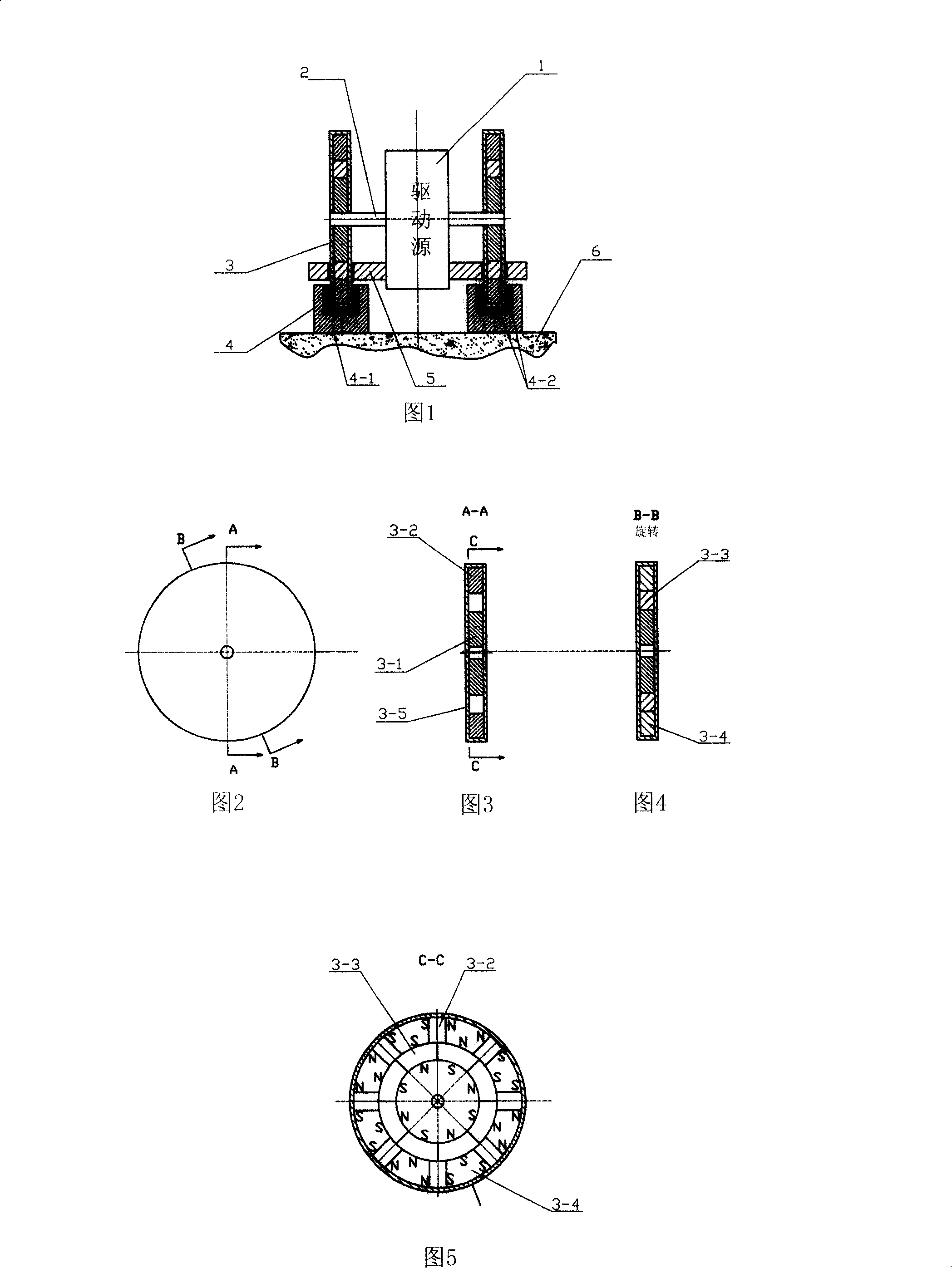
[0068] Specific implementation mode one: as shown in Figure 1 to Figure 9 shown.

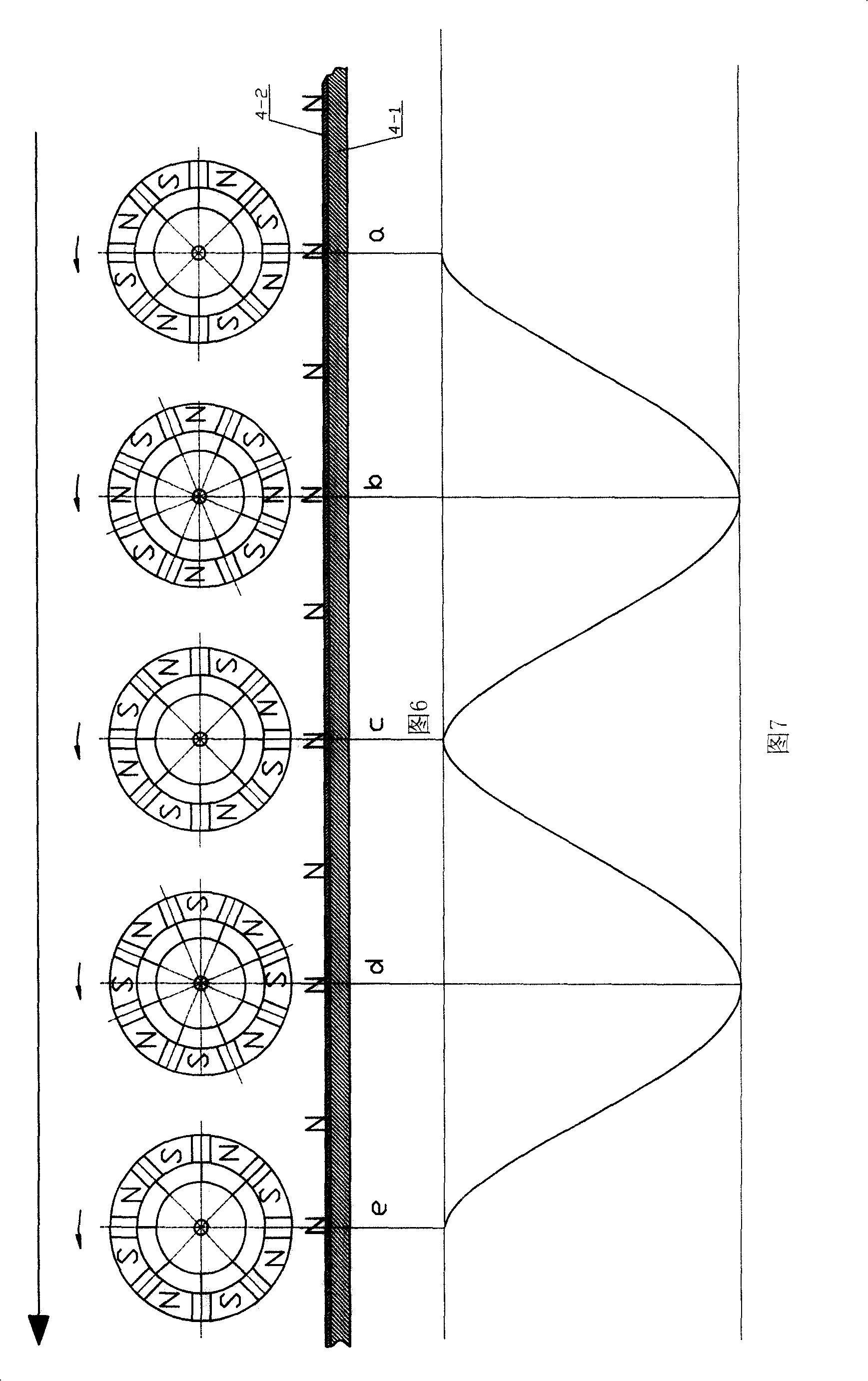
[0069] The magnetic wheel 3 is composed of a magnetic conduction disk 3-1, a tile-shaped permanent magnet block 3-3 magnetized in the radial direction, a permanent magnet block 3-2 magnetized in a tangential direction, a fan-shaped magnetic conduction block 3-4 and a non-conductive magnetic block 3-4. The magnetic material cladding plate 3-5 is assembled and consolidated as shown in Figure 2 to Figure 4, and the permanent magnetic block 3-3 of the tile can also be partitioned along the circumferential direction with the integral permanent magnetic ring, and the multi-pole polarity is alternated along the radial direction Manufactured by magnetization, the circumferential interface of the tile-shaped permanent magnet block 3-3 and the neutral plane of the permanent magnet block 3-2 are on the same radial line of the magnetic wheel 3, and perpendicular to the end face of the magnetic wheel 3, Ad...

specific Embodiment approach 2

[0072] Specific embodiment two: as shown in Fig. 10 to Fig. 20 .

[0073] The cross-section of the magnetically permeable base 10-1 of the track 10 is made into a rectangle, and the permanent magnet plate 10-2 that is magnetized along the thickness direction is consolidated on the top, the left side, and the right side; The right three magnetic wheels are combined and connected, and then encapsulated and consolidated with non-magnetic material plates 9-7. The left and right magnetic wheels are parallel and symmetrical, and the structure and material of the middle magnetic wheel are completely the same as the magnetic wheel in the specific embodiment one; 2. The permanent magnet block 9-5 magnetized along the tangential direction, the sector-shaped magnetic block 9-8, and the sector-shaped permanent magnet block 9-9 magnetized along the axial direction (thickness) are combined and consolidated, wherein the adjacent The permanent magnet blocks 9-5 are relatively opposite with t...

specific Embodiment approach 3

[0075] Specific embodiment three: as shown in Fig. 21 to Fig. 28 .

[0076] The magnetically conductive track seat 13-1 of the track 13 is made with a V-shaped groove in the middle of the top, and a permanent magnet plate 13-2 magnetized along the thickness direction is consolidated in the V-shaped groove; as shown in Figures 22 to 27, the magnetic wheel 12 Consists of non-magnetic cylinder 12-1, discus-shaped magnetizer 12-3, sector-shaped magnetizer block 12-2, permanent magnet block 12-4 magnetized along the tangential direction and sector-shaped permanent magnet block 12 magnetized along the thickness direction -5 and non-magnetic material cladding plate 12-6 are combined and consolidated; the manufacturing method of the sector-shaped permanent magnet block 12-5 is similar to that of the sector-shaped permanent magnet block 9-9 of the magnetic wheel 9 described in the second embodiment , the only difference is that the sector-shaped permanent magnet block 9-9 is flat, and ...


PUM


Abstract

The invention provides a permanent magnetic suspension and magnetic wheel propulsion vehicle. The symmetrical centre of the soleplate of a car body is provided with a driving source, and magnetic wheels are symmetrically fixed at the left and the right of the extended shaft; a rail which is fixed on a roadbed is arranged just below each magnetic wheel; the permanent magnetic plates which are filled with magnetism in thickness direction are consolidated on the rail; the bottom of the car body stands aside a soft magnetic wheel along the extension direction of the rail; the permanent magnetic plate on the vehicle which is arranged in parallel and has the same polarity and the rail permanent magnetic plate is arranged a clearance away from the rail; one part of the magnetic plate and the permanent magnetic plate of the car body are inserted into the trough of the rail but keep a clearance away from the trough wall in order to be not contacted with the trough; alternatively, both the magnetic wheel and the permanent magnetic plate on the vehicle span above the rail by keeping a clearance with the rail; the vehicle is suspended and guided due to a magnetic repulsive force, and the driving source drives the soft magnetic wheel to rotate to generate magnetic force function with the rail, so as to propel the vehicle.

Description

technical field [0001] The invention relates to a magnetic suspension vehicle, in particular to a permanent magnetic suspension and magnetic wheel propulsion vehicle. Background technique [0002] Magnetic levitation vehicles have excellent performances such as non-contact, low vibration, low noise, safety, speed, low energy consumption, and high efficiency. The maglev train technology in Japan and Germany is at the forefront, especially the maglev train in Germany has been extended to commercial operation. According to the levitation mode, the maglev vehicles are divided into suction-floating type and repelling-floating type. Germany adopts the constant conduction suction floating type, while Japan adopts the superconducting repellent floating type. The so-called constant guide suction floating type is to use the electromagnet arranged on the train to attract the magnetic track arranged below the roadbed, so that the train is suspended and guided, and it is propelled by a...

Claims


Application Information

Patent Timeline
Patent Type & Authority Applications(China)
IPC IPC(8): B60L13/10B61B13/00
Inventor 刘新广
Owner 刘新广
Why Eureka
Try Eureka