

Bobbin bracket structure of transformer
A winding frame and transformer technology, applied in the direction of transformer/inductor coil/winding/connection, inductor/transformer/magnet manufacturing, coil manufacturing, etc., can solve the problem of volume limitation of winding frame 2, and increase coil routing Effects of distance, increased withstand voltage, and reduced thickness
- Summary
- Abstract
- Description
- Claims
- Application Information
AI Technical Summary
Problems solved by technology
Method used
Image

Examples
Embodiment Construction
[0021] In order to enable your review committee to further understand the technology, means and effects of the present invention to achieve the intended purpose, please refer to the following detailed description and accompanying drawings of the present invention. It is believed that the purpose, characteristics and characteristics of the present invention can be obtained from this To gain a deep and specific understanding, the attached drawings are only for reference and illustration, and are not intended to limit the present invention.
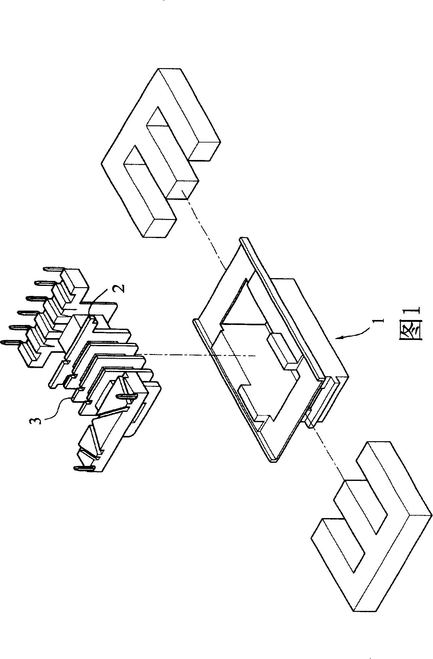
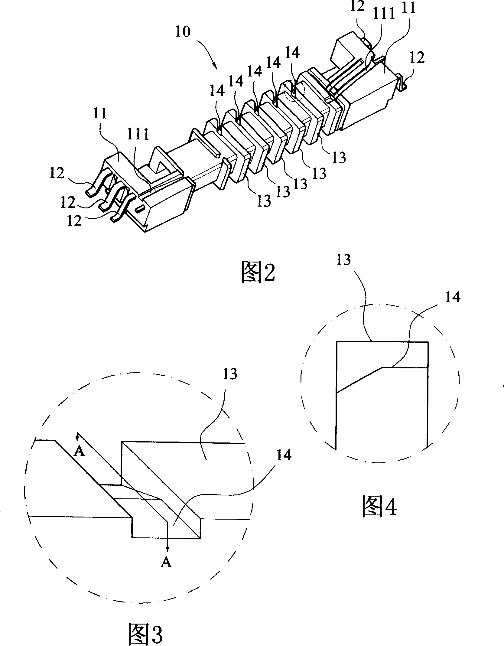
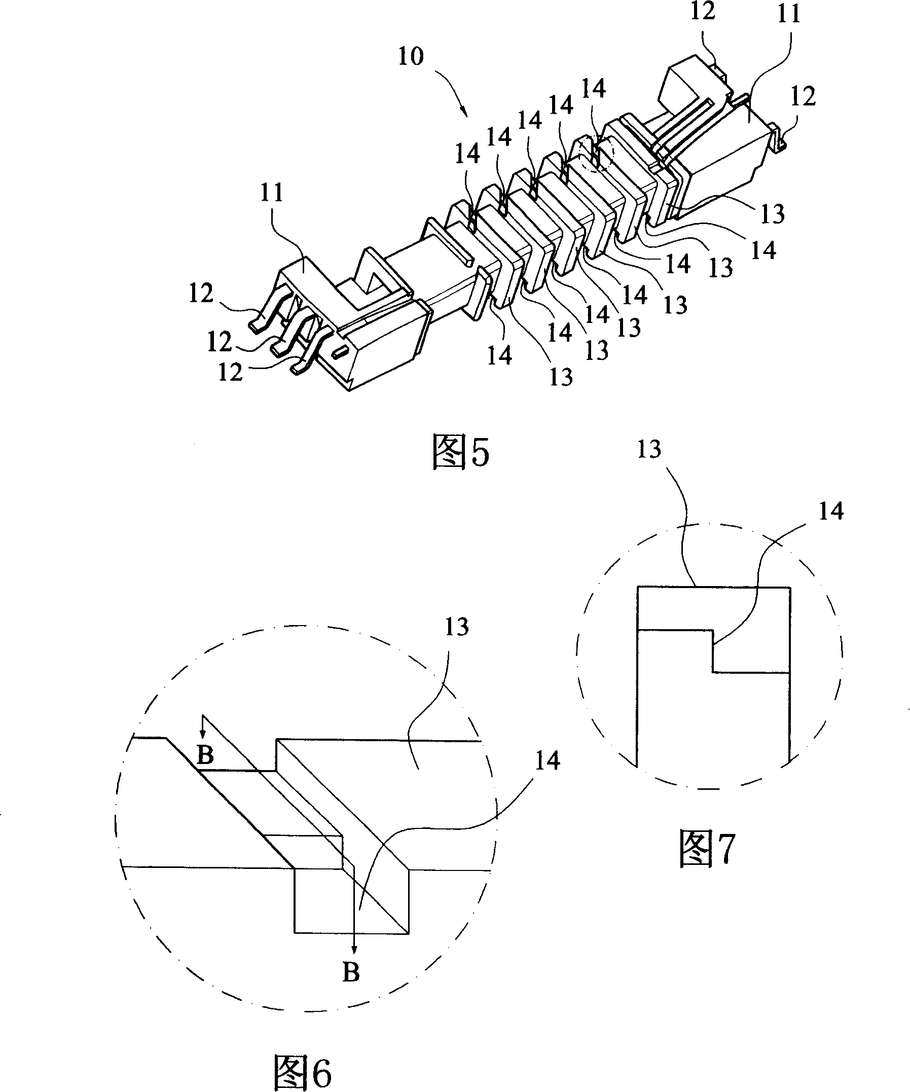
[0022] Referring to Fig. 2, it is a three-dimensional schematic view of the first embodiment of the transformer bobbin of the present invention. The transformer bobbin 10 of the embodiment of the present invention is in the shape of a hollow tube, on which multiple groups of coils can be wound (not shown in the figure) ), two ends are provided with a tube base 11, and a plurality of electrical pins 12 are embedded on the outside of the tube b...
PUM
 Abstract
Description
Claims
Application Information