Mobile joint unit for switch and switch device using the same

A switch device and moving contact technology, which is applied to electrical switches, electrical components, optical components, etc., can solve the problems that the operation keys cannot be illuminated by enough light, diffuse reflection, etc., achieve good assembly workability, reduce light leakage, reduce The effect of manufacturing cost and power consumption

Active Publication Date: 2008-07-02
ALPS ALPINE CO LTD
View PDF1 Cites 5 Cited by
  • Summary
  • Abstract
  • Description
  • Claims
  • Application Information

AI Technical Summary

Problems solved by technology

However, it was found that when the flexible light guide plate 103 is laminated on the flexible plate 101, since the two are in close contact, as shown by the arrow in the figure, a part of the light introduced into the light guide plate 103 from the side end surface Leakage into the

Method used


Image

  • Mobile joint unit for switch and switch device using the same
  • Mobile joint unit for switch and switch device using the same
  • Mobile joint unit for switch and switch device using the same

Examples


Embodiment Construction

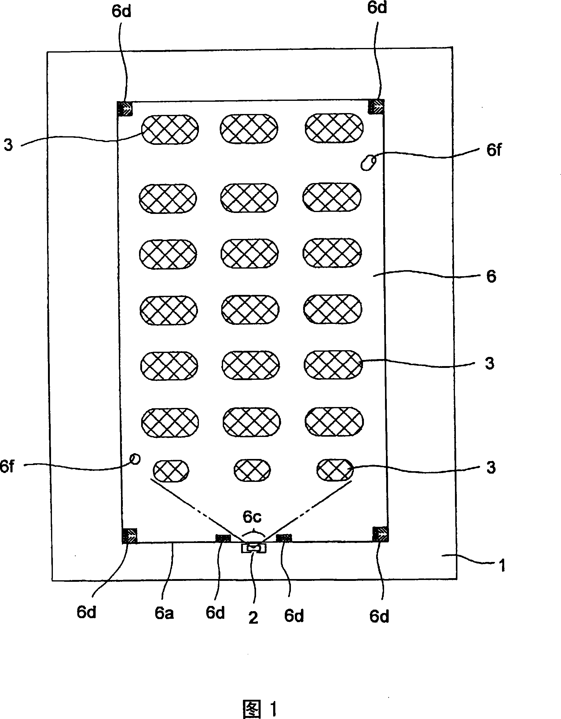
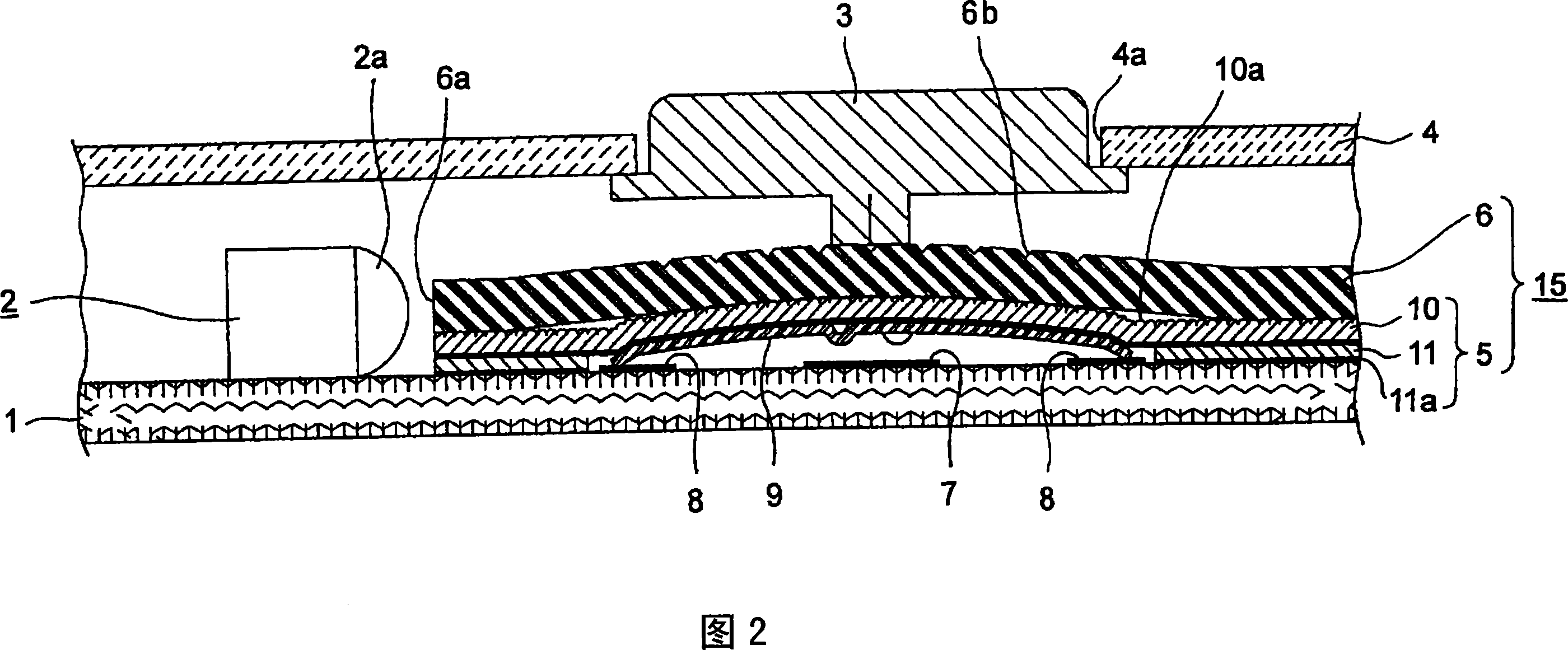
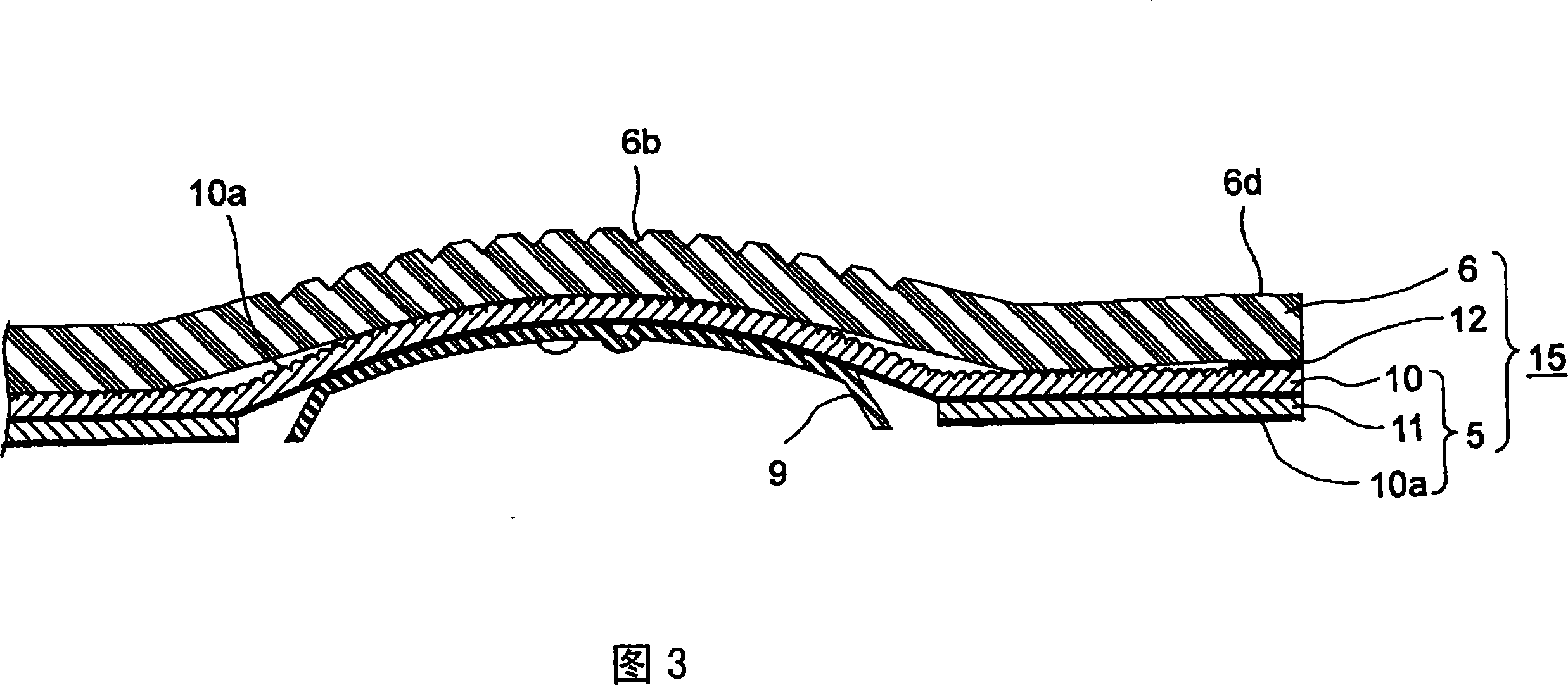
[0036] Embodiments of the present invention will be described with reference to the accompanying drawings. FIG. 1 is a plan view showing a switchgear according to a first embodiment of the present invention without a cover, FIG. 2 is a sectional view of a main part of the switchgear, and FIG. 3 is a view of the switchgear. A cross-sectional view of the main part of the movable contact unit used, FIG. 4 is an enlarged view of the air reservoir provided in the movable contact unit viewed from obliquely above, and FIG. 5 shows a flexible light guide plate in the movable contact unit An explanatory diagram of the route of light propagating inside.

[0037] The switch device shown in these figures mainly includes: a substrate 1 on which LED 2 is mounted; a plurality of operation keys 3 disposed in an opening 4a of a cover case 4; a plate member 5 with contacts placed on the substrate 1; The flexible light guide plate 6 on the plate member with contact 5 ; the plate member with cont...


PUM


Abstract

To provide a movable contact unit for a switch capable of having suitable assembling operability and reducing manufacturing costs and power consumption and restraining diffused reflection at an undesirable zone and having suitable illumination quality, and to provide a switch device using the movable contact unit. An LED 2 as a light source is mounted on a board 1, an emitting section 2a of the LED 2 is made opposed to a side end face 6a of a flexible light guide plate 6, and light guided from the LED 2 into the flexible light guide plate 6 is projected on a bottom surface of an operation key 3 via an illuminating section 6b of the light guide plate 6. The flexible light guide plate 6 is laminated on a flexible sheet 10 of a sheet member 5 with contacts, and a group of movable contacts 9 are glued and retained on a lower surface of the flexible sheet 10. An air space (non-sticking section) 10a is also arranged between the flexible sheet 10 and flexible light guide plate 6.

Description

technical field [0001] The present invention relates to a movable contact unit for a switch incorporated in a switch device with a lighting function provided with a plurality of switch elements independently pressed and driven by a plurality of operation keys, and a switch using the movable contact unit for a switch device. Background technique [0002] For example, in the input unit of a mobile phone, etc., in order to enable the operation key group for independently pressing and driving a plurality of switch elements to be recognized in the dark to achieve good usability, in many cases, it is assembled with a A lighting device that projects light onto an operation key group to illuminate characters, marks, etc. of the operation key group. As a conventional example of such a switch device with a lighting function, a well-known structure is to mount a light source such as an LED near each bottom surface of the operation key group on a substrate on which the switch element g...

Claims


Application Information

Patent Timeline
IPC IPC(8): H01H13/02H01H13/70H01H9/18G02B6/00
CPCH04M1/22H04M1/23
Inventor 斋藤充岩间尚也
Owner ALPS ALPINE CO LTD
Why Eureka
Try Eureka