Motor position sensor

A sensor and motor technology, applied in the field of motor position sensors that change the winding structure, can solve the problems of destroying the structure of the axis A1, increasing the vibration coefficient, and repairing the damaged motor A, so as to reduce the cooperation of transformers and save maintenance Effects of cost and weight reduction

Inactive Publication Date: 2008-07-02
HIWIN MIKROSYST
View PDF0 Cites 5 Cited by
  • Summary
  • Abstract
  • Description
  • Claims
  • Application Information

AI Technical Summary

Problems solved by technology

[0004] First, when the main body rotor P31 of the main body P30 of the resolver P10 and the transformer rotor P21 of the transformer P20 rotate coaxially, the two are electrically connected for trigger signal transmission, as the main body rotor P31 of the main body P30 and the transformer rotor When the P21 rotates, it is easy to break the line and cause the signal to disappear, so it cannot work normally
[0005] Second, the weight of the transformer P20 of the resolver P10 and the main body P30 on the axis A1 of the motor A will also cause a burden on the operation of the axis A1 of the motor A. Long-term operation will increase the vibration coefficient of the motor A and damage the axis. The core A1 structure makes the motor A internally damaged and needs to be repaired and costly

Method used


Image

  • Motor position sensor
  • Motor position sensor
  • Motor position sensor

Examples


Embodiment Construction

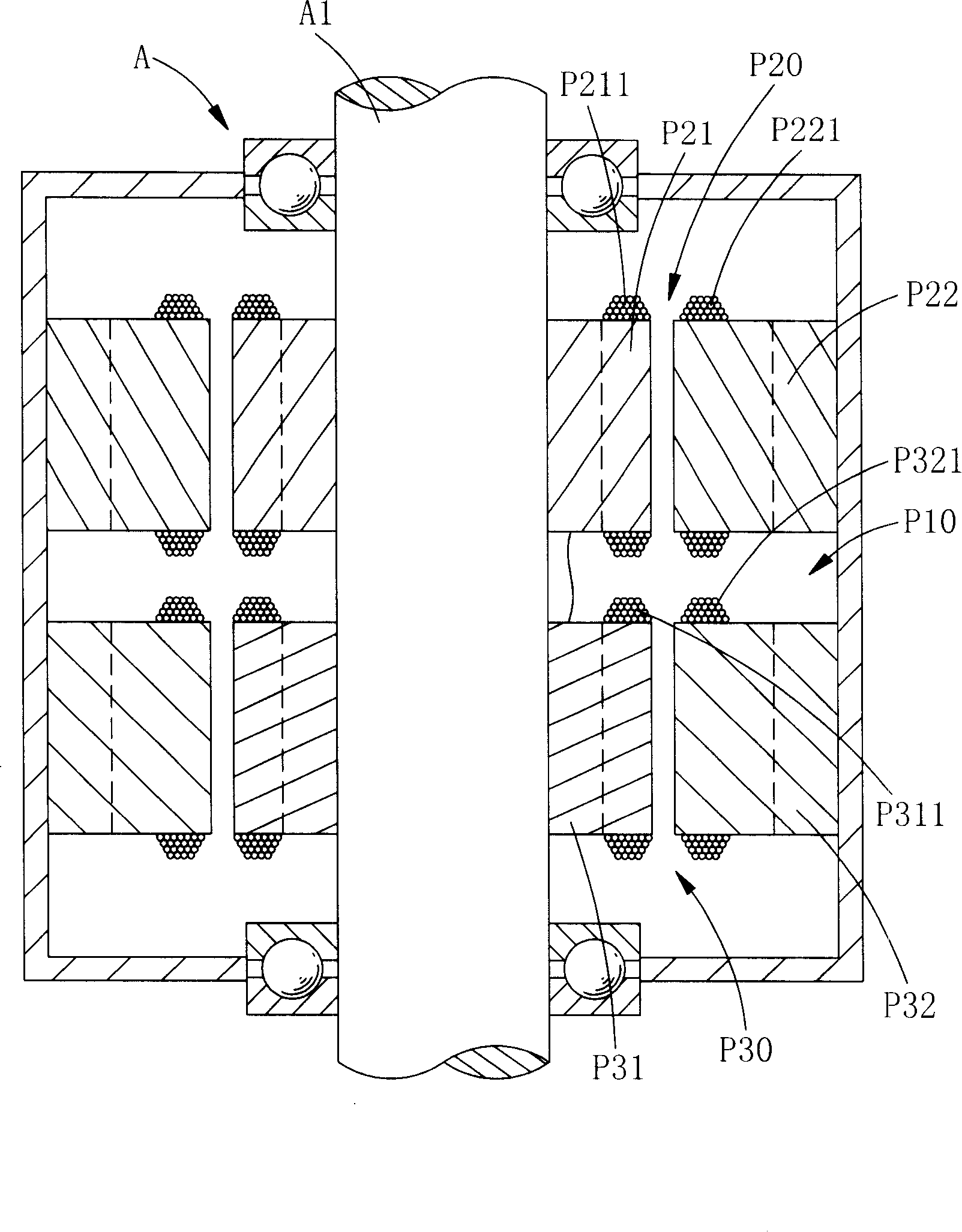
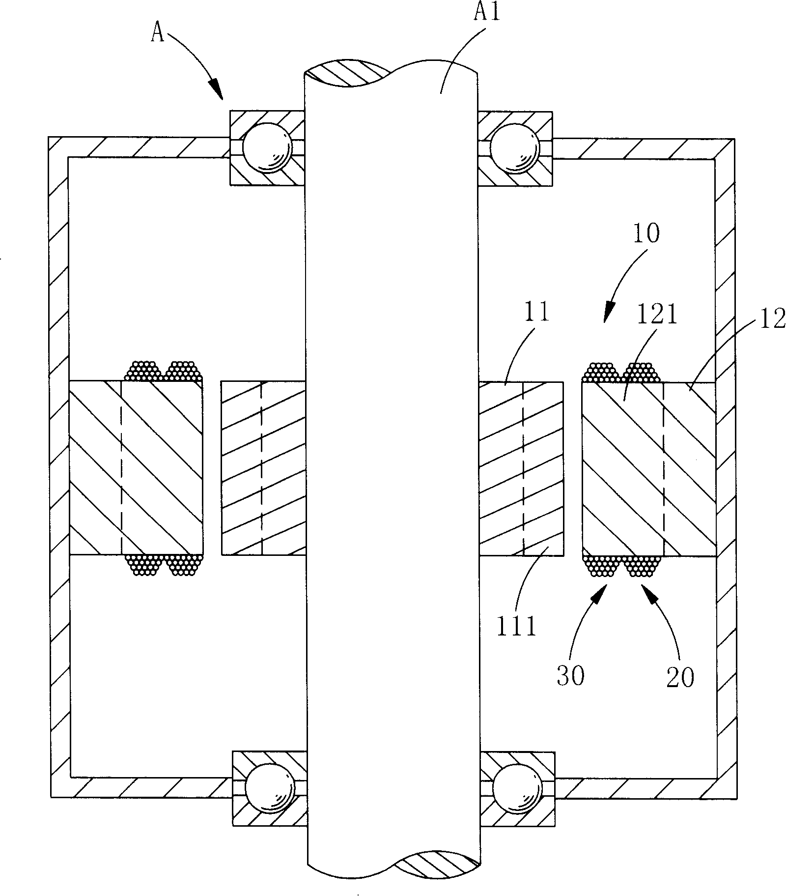
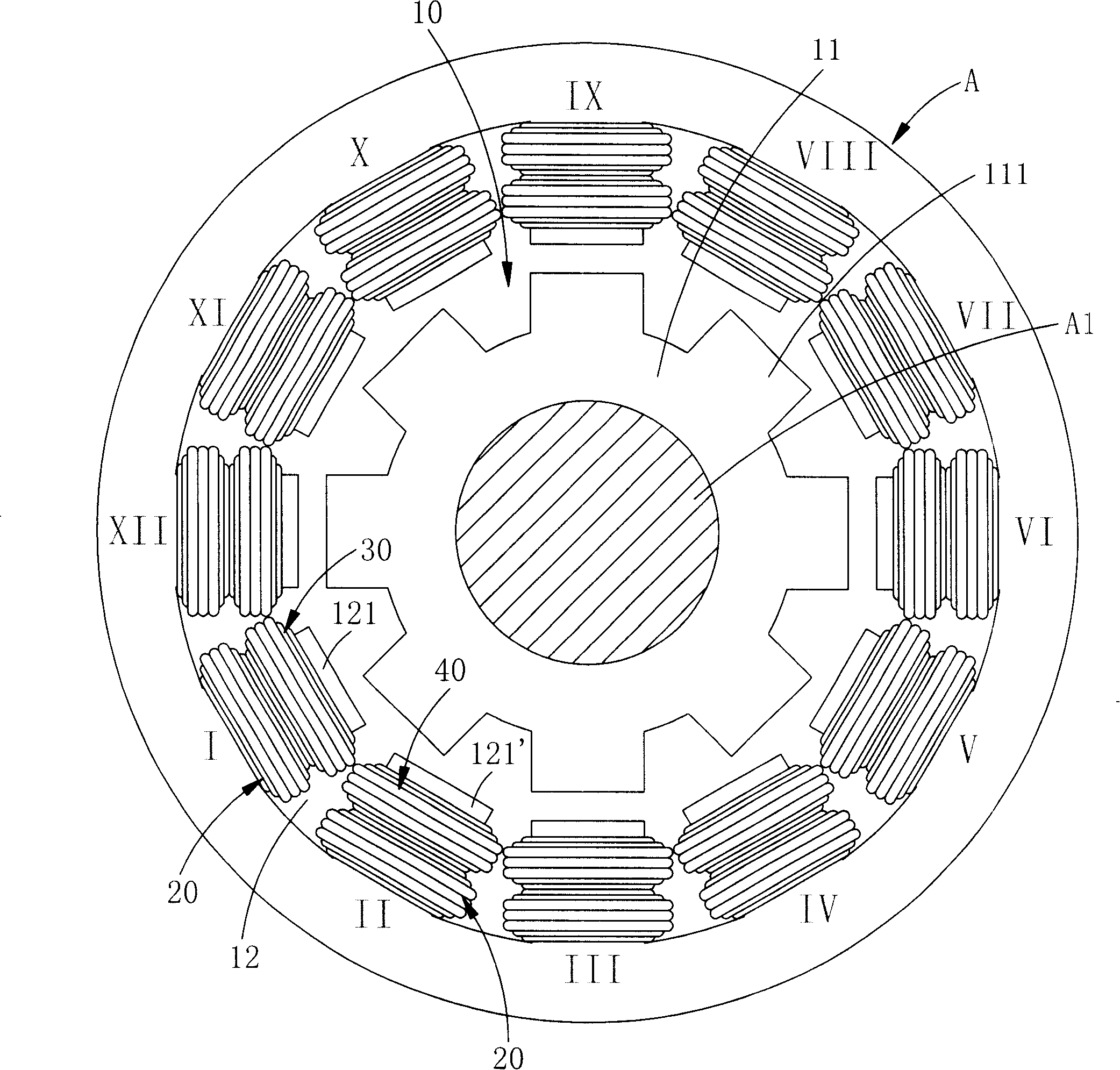
[0044] Please refer to the embodiment of the present invention figure 2 , image 3 Shown:

[0045] The motor position sensor of the present invention includes a resolver 10, a plurality of trigger coils 20, a plurality of sine coils 30 and a plurality of cosine coils 40; the resolver 10 is installed inside the motor A, and the resolver 10 includes a body 101, the The main body 101 includes a main body rotor 11 and a main body stator 12, the main body rotor 11 is annular, the main body rotor 11 is placed on the axis A1 of the motor A, and a plurality of rotor magnetic poles are set around the main body rotor 11 at equidistant intervals 111 The main body stator 12 is ring-shaped, and the main body stator 12 is fixed on the inner wall of the motor A, and a plurality of stator poles 121 are arranged at equal intervals around the main body stator 12; A set of trigger coils 20 is wound, and a set of sinusoidal coils 30 are wound adjacent to the trigger coils 20. A set of trigger ...


PUM


Abstract

The invention relates to a motor position sensor, which includes a resolver and a plurality of trigger coils; wherein, the reslover includes a body and the body includes a body rotator and a body stator; the body stator is wound and arranged on the trigger coil to sense a position angle and judge a start angle and conduce suitable current; besides, the body rotator does not needed to be wound so as to further reduce weight load of a motor axes and facilitate the reliability as well.

Description

technical field [0001] The invention relates to a motor position sensor, in particular to a motor position sensor which changes the winding structure. Background technique [0002] According to the current motor A (such as figure 1 The resolver (RESOLVER) P10 set on the shown) includes a transformer P20 and a body P30; the transformer P20 is composed of a transformer rotor P21 and a transformer stator P22; the transformer rotor P21 is annular, and the transformer rotor P21 wears Placed on the axis A1 of the motor A, a number of coils P211 are placed around the transformer rotor P21; the transformer stator P22 is ring-shaped, and the transformer stator P22 is fixed on the inner wall of the motor A; A number of coils P221 are placed around the coil, corresponding to the coil 211 of the transformer rotor P21; the main body P30 is composed of a main body rotor P31 and a main body stator P32; the main body rotor P31 is annular, and the main body rotor P31 is placed on the A shaf...

Claims


Application Information

Patent Timeline
IPC IPC(8): H02K29/06H02P6/16H02P6/17
Inventor 卓永财苏奕丞李明芫
Owner HIWIN MIKROSYST
Why Eureka
Try Eureka