Automatically coiling method for overlength sheath spring

A winding method and sheath technology are applied in the field of spring manufacturing technology, which can solve the problems of high mandrel length and high mandrel winding cost, achieve uniform spring pitch, save winding spring fixtures and special tools, and spring geometric dimensional accuracy. high effect

Inactive Publication Date: 2008-07-09
CHANGAN AUTOMOBILE (GRP) CO LTD
View PDF0 Cites 30 Cited by
  • Summary
  • Abstract
  • Description
  • Claims
  • Application Information

AI Technical Summary

Problems solved by technology

[0003] In order to overcome the shortcomings of high winding cost and long mandrel for winding super-long helical sheath spring

Method used


Image

  • Automatically coiling method for overlength sheath spring
  • Automatically coiling method for overlength sheath spring

Examples


Embodiment Construction

[0011] Below in conjunction with accompanying drawing and example the patent of the present invention is further described.

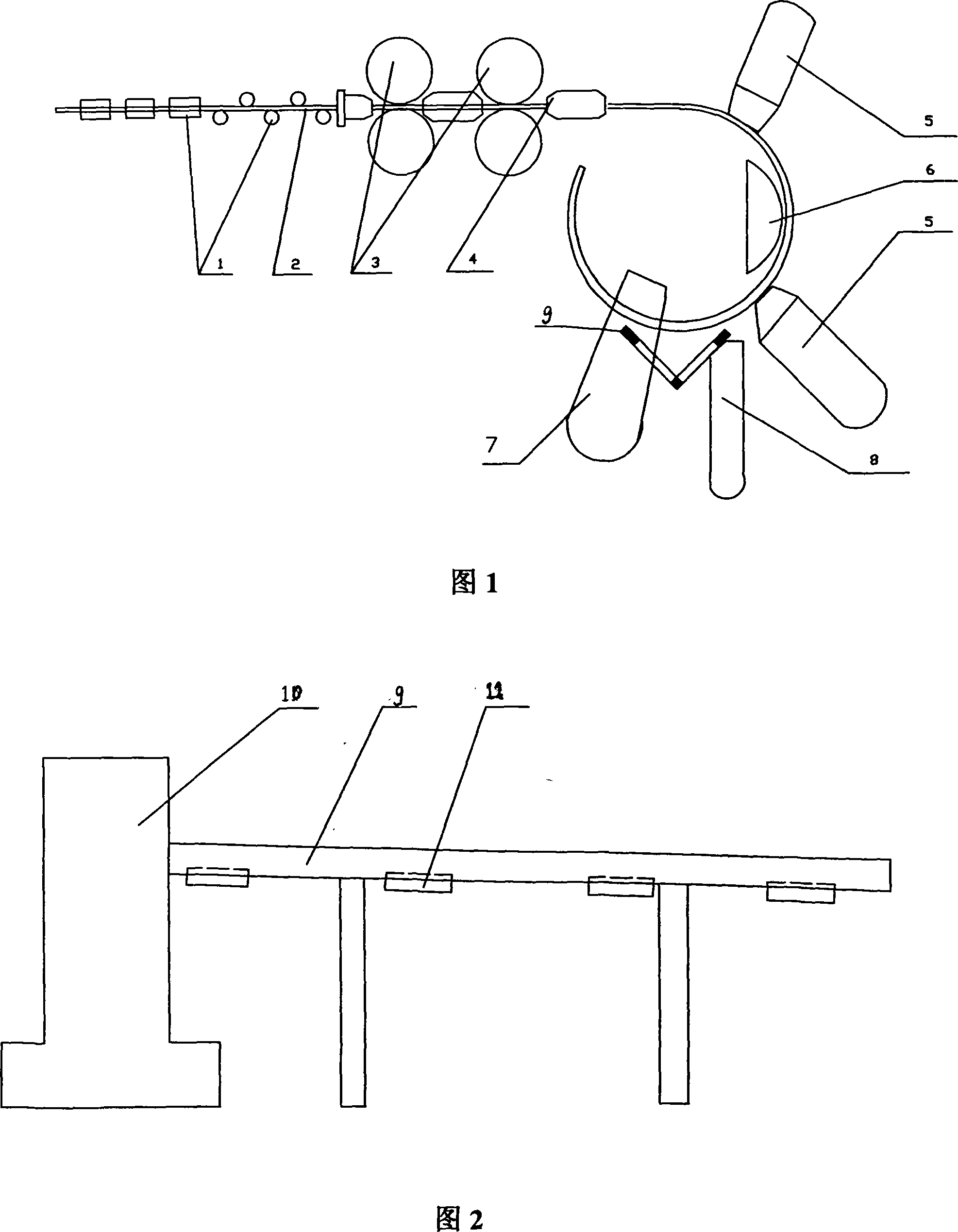
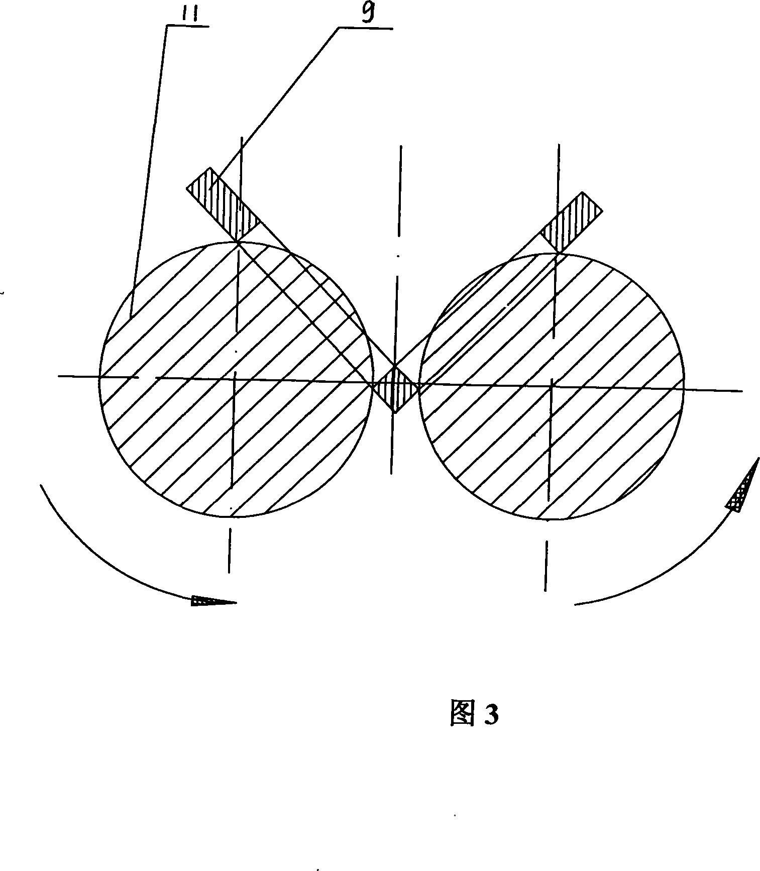
[0012] Refer to Figure 1, Figure 2 and Figure 3, install the ¢2mm steel wire on the material rack of the automatic spring winding machine (model: Z53-8), pass it through the straightening roller group, the feeding roller group and the guide wire groove plate, Adjust the winding outer diameter and pitch of the spring. If it does not meet the requirements, continue to adjust various parameters until a qualified sheath spring sample is wound. After passing the inspection, the normal sheath spring winding can be started. system. After the steel wire 2 is straightened by the straightening roller 1, it is driven by the feed roller 3 to pass through the guide wire groove plate 4, and is forced to bend into a circular arc by the coil spring rod 5. The steel wire 2 is formed by two coil springs at 60° The rod 5 revolves in a helical circle around the mandrel kn...


PUM


Abstract

The invention relates to a self coiling method for an ultra-long protecting sleeve spring which leads a spring steel wire into an automatic spring coiling machine through an aligning mechanism, a rolling wheel and a guiding plate to bend and coil to make into a spiral spring ring; the spring ring that is coiled extends outward rotatably along a V-shaped slot orbit arranged in a discharge port of the automatic spring coiling machine and is driven by a plurality of pairs of rolling wheels mounted on the V-shaped slot orbit to rotate deasil along the rolling wheels or two operating workers stand at two sides of the V-shaped orbit and use hand to deasil turnover the spring that is coiled ceaselessly until the protecting sleeve spring is finished to be coiled. The coiled spring of the invention has higher automation and manufacture quality of the protecting sleeve spring, uniform node distance of the spring and higher precision on the physical dimension of the spring; compared with the adopting a manual coiling by a latch, the invention can save massive spring coiling clampers and special tools as well as greatly save the working intensity of workers.

Description

Technical field: [0001] The invention relates to spring manufacturing technology. Background technique: [0002] Coil spring manufacturing is generally divided into coil springs with a mandrel and coil springs without a mandrel. The manufacturing feature of a coil spring with a mandrel is that the mandrel is mounted on the chuck of the main shaft of the lathe, and rotates with the main shaft. The main shaft passes through the hanging wheel and feeds The lead screw makes the feeding device of the spring material move left and right on the bed, and the spring material is wound tightly around the mandrel to form a spring. The mandrelless coil spring manufacturing process is realized by an automatic spring coiling machine. After the spring steel wire is drawn out from the material tray frame, it enters the winding mechanism through the straightening mechanism, rollers, and guide plates. The winding rod withstands it, revolves around the mandrel knife in a spiral circle, and is ...

Claims


Application Information

Patent Timeline
IPC IPC(8): B21F3/02
Inventor 付在再
Owner CHANGAN AUTOMOBILE (GRP) CO LTD
Why Eureka
Try Eureka