Controllable siphon discharging device and operation method for reservoir drainage or flood discharge

A discharge device and a controllable technology, applied in siphons, water conservancy projects, sea area projects, etc., can solve the problems of limited reservoir capacity, limited spillway flood discharge capacity, easy leakage, etc., to increase the effective height and reservoir capacity, improve Safety and mobility, and the effect of increasing power generation capacity

Inactive Publication Date: 2008-07-09
胡立文
View PDF0 Cites 13 Cited by
  • Summary
  • Abstract
  • Description
  • Claims
  • Application Information

AI Technical Summary

Problems solved by technology

Reservoirs with a small design scale are difficult to withstand this pressure, and dangerous situations occur. Most of the reasons for dangerous situations are due to the limited capacity of the reservoir, the limited flood discharge capacity of the spillway, and the inconvenience of flood discharge in advance. Spillways are generally rectangular. To design a large and reasonable cross-sectional area, it is necessary to have a certain height, and its height has no effect or help on the storage capacity of the reservoir, but this height is not available around the reservoir, which is obviously a waste, and is narrow and long The rectangular cross-section is not ideal for the flow rate and flow rate of water, which is poor, so the overflow capacity is also low. In addition, the water discharge valve is generally a traditional gate valve, which is simple and rough. , the gate is stressed, and the friction force increases after the two sides contact. It is laborious and troublesome for farmers to open the gate when they need to deliver water for irrigation or to release floods in advance. Manpower and material resources are used for maintenance, repair and management, which is backward, uneconomical, and prone to leakage

Method used


Image

  • Controllable siphon discharging device and operation method for reservoir drainage or flood discharge

Examples


Embodiment 1

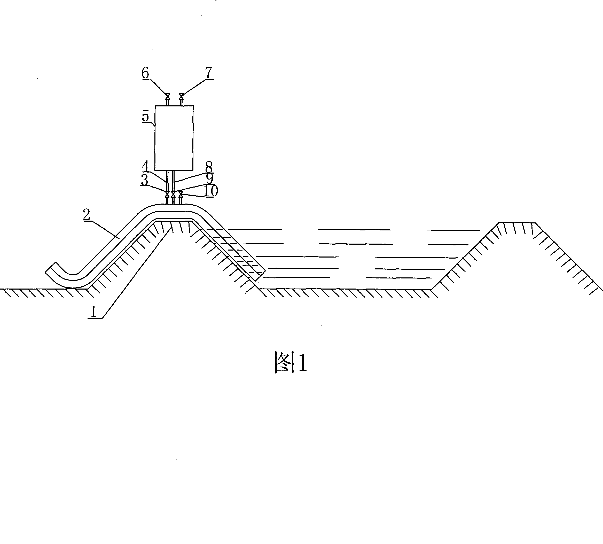
[0019] Controllable siphon discharge device used for reservoir drainage or flood discharge, including dam body 1, siphon pipe 2, air outlet valve 3, air outlet pipe 4, water inlet pipe 8, water inlet valve 9, inlet pipe with valve 10, gas-liquid separator 5 , Water-filling pipe 7 with valve, vent valve 6, dam body 1 is equipped with siphon pipe 2, the inlet end of siphon pipe 2 is located at the lower part of the reservoir dam body, the outlet end has an elbow located at the lower part of the reservoir dam body body, and the middle part is located at the top of dam body 1 , the siphon pipe 2 is equipped with an air inlet pipe 10 with a valve, the siphon pipe 2 is connected with the gas-liquid separator 5 through the air outlet pipe 4 and the water inlet pipe 8, the air outlet pipe 4 is equipped with an air outlet valve 3, the water inlet pipe 8 is equipped with a water inlet valve 9, and the gas The upper part of the liquid separator is equipped with a vent valve 6 and a water ...


PUM


Abstract

A controllable siphon drainage device of reservoir drainage and flood discharging of the invention comprises a dam body, a siphon pipe, a gas outlet valve, a gas outlet pipe, a water inlet pipe, a water inlet valve, a gas inlet pipe provided with a valve, a gas-liquid separator, a water charging pipe provided with a valve and a purge valve. The invention is characterized in that: the dam body is provided with a siphon pipe, the entrance end of the siphon is arranged in the lower part inside the reservoir dam body, the exit end of the siphon is provided with an elbow arranged in the lower part outside the reservoir dam, the middle part of the siphon is arranged on the top of the dam body, the siphon pipe is provided with a gas inlet pipe with a valve, the siphon pipe is connected to the gas-liquid separator through the gas outlet pipe and the water inlet pipe, the gas outlet pipe is provided with a gas outlet valve, the water inlet pipe is provided with a water inlet valve, the top end of the gas-liquid separator is provided with a purge valve and a water charging pipe with a valve. The invention has the advantages of simple operations, convenience and quickness, work-saving and labor-saving; can improve the effective height, reservoir capacity, flood charging and discharging and normal drainage ability, thereby improving the reservoir safety and flexibility.

Description

technical field [0001] The invention relates to a mechanical device and operation method for reservoir drainage or flood discharge, in particular to a controllable siphon discharge device and operation method for reservoir drainage or flood discharge. Background technique [0002] In the process of people's production and life, water is a kind of non-renewable material resource that human beings rely on for survival, and the reservoir is a large container to ensure that water resources will not be lost. The effective height of its dam will directly affect the capacity of the reservoir. The spillover discharge capacity and method directly affect the effective height and safety of the dam, so the spillover discharge capacity and method are of great significance to the safety and water storage capacity of the reservoir during operation. [0003] In order to ensure the normal operation of the reservoir, the reservoir is generally located near the downstream between two mountains...

Claims


Application Information

Patent Timeline
Patent Type & Authority Applications(China)
IPC IPC(8): E02B8/06F04F10/00
Inventor 胡立文
Owner 胡立文
Why Eureka
Try Eureka