
Needle fin tube and plain tube mixedly arranged self-supporting type heat exchanger

A pin-fin tube, self-supporting technology, applied in heat exchanger types, indirect heat exchangers, fixed tubular conduit components, etc., can solve the problem of reducing the mass flow rate of effective flushing pin-fin tubes, and the limitation of heat transfer capacity of type heat exchangers , pin-fin tube and shell side bypass flow, etc., to achieve the effect of solving tube bundle oscillation, improving heat transfer coefficient, and increasing heat transfer process

Inactive Publication Date: 2008-07-09
HARBIN ENG UNIV
View PDF1 Cites 16 Cited by
  • Summary
  • Abstract
  • Description
  • Claims
  • Application Information

AI Technical Summary

Problems solved by technology

The patent application document with the patent number 00220040.6 provides a "pin-fin tube heat exchanger", which uses pin-fin tubes to replace the original light tubes to enhance heat transfer. However, when this type of heat exchanger is used to cool lubricating oil, due to the viscosity Higher, prone to bypass flow between pin-fin tube and shell side
Bypass flow will reduce the mass flow rate that effectively flushes the pin-fin tubes, thereby limiting the heat transfer capacity of this type of heat exchanger
In addition, there is no support plate between the pin-fin tubes. When the high-velocity fluid flushes the pin-fin tube bundle, it is easy to induce vibration of the heat exchange tubes and shorten the service life of the heat exchanger.

Method used


Image

  • Needle fin tube and plain tube mixedly arranged self-supporting type heat exchanger
  • Needle fin tube and plain tube mixedly arranged self-supporting type heat exchanger
  • Needle fin tube and plain tube mixedly arranged self-supporting type heat exchanger

Examples


Embodiment Construction

[0033] The present invention is described in more detail below in conjunction with accompanying drawing example:

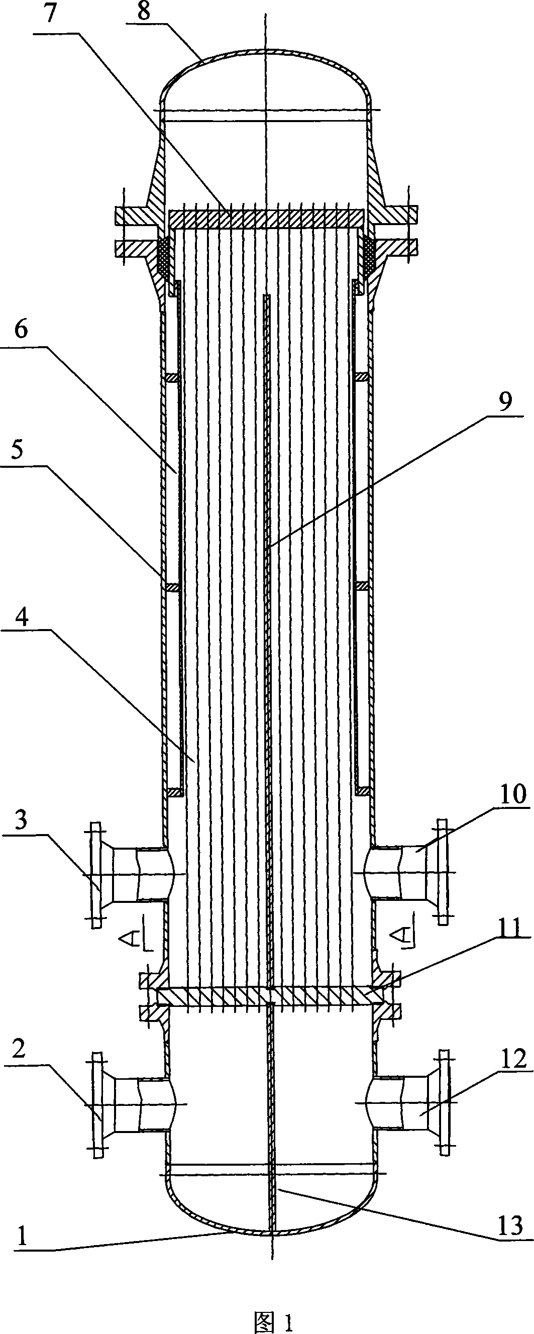
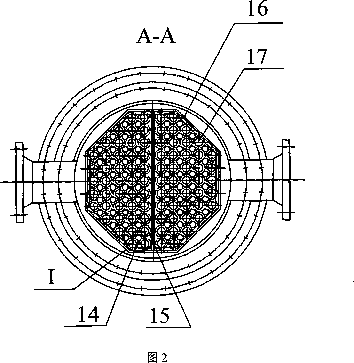
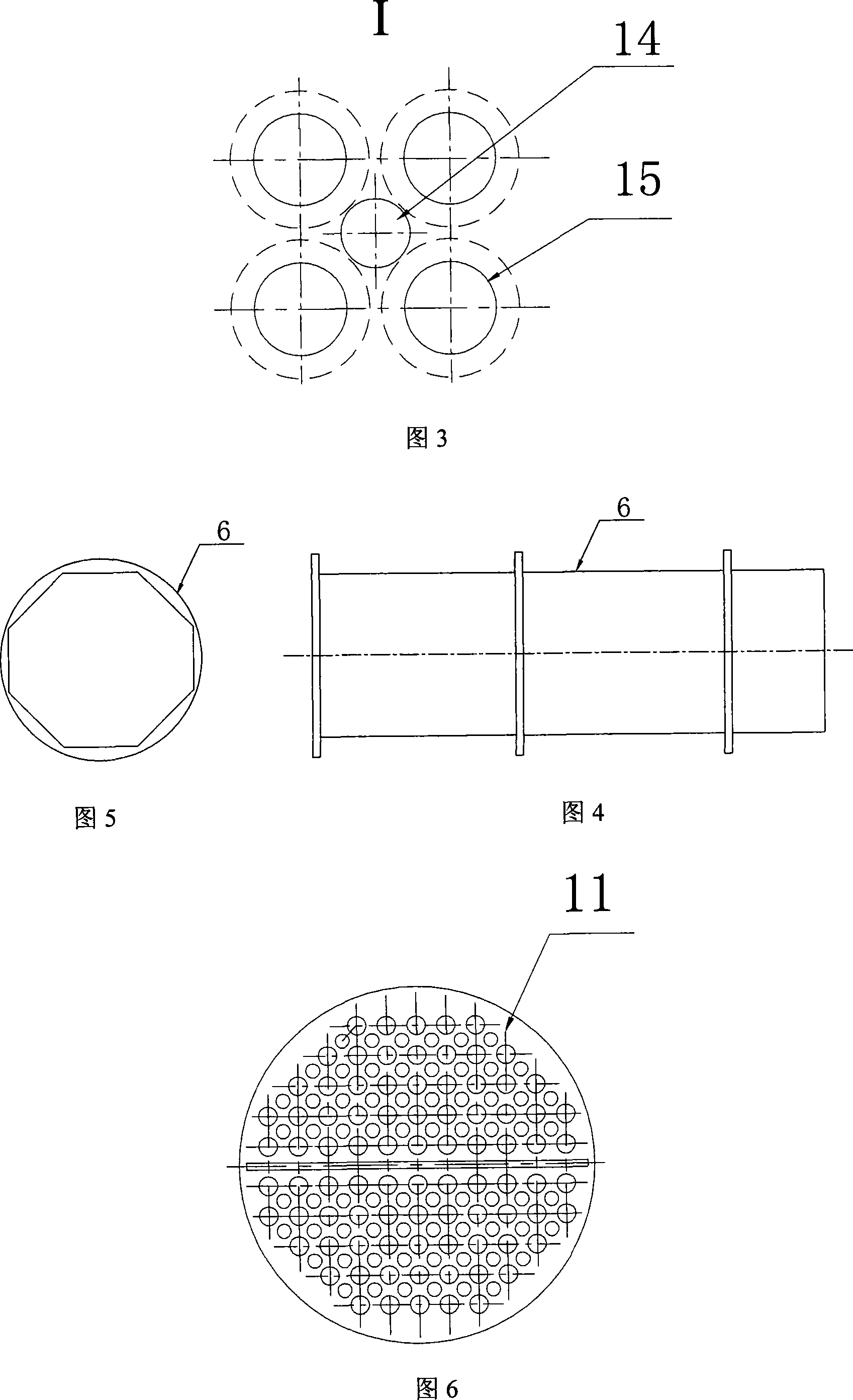
[0034] Combined with Figure 1, the self-supporting heat exchanger composed of pin-fin tubes and bare tubes is composed of a shell 3 and a tube bundle 4 installed in the shell. The two ends of the tube bundle are respectively installed on the fixed tube plate 11 and the floating head tube plate 7 , the fixed tube plate 11 is fixedly installed between the lower end of the shell and the tube box 1, the upper end of the shell 3 is equipped with an upper head 8, the shell has a shell side inlet 10 and a shell side outlet 3, and the tube box 1 has a The tube-side inlet 2 and the tube-side outlet 12, the tube bundle 4 is a mixed arrangement of bare tubes and pin-fin tubes with high-efficiency heat exchange capacity. Combined with Fig. 2 and Fig. 3 at the same time, the mixed arrangement of the light pipes and the pin-fin tubes with high-efficiency heat exchange capacity ...


PUM


Abstract

The invention provides a self-support type heat exchanger with mixed arrangement of pin-fin tubes and bare tubes, which comprises a shell, a tube bundle disposed inside the shell, wherein the two ends of the tube bundle are respectively disposed on a fixed tube plate and a floating tube plate, the fixed tube plate is fixedly installed between the lower end of the shell and a channel, an upper header is disposed at the upper end of the shell, a shell pass inlet port and a shell pass outlet port are disposed on the shell, a tube pass inlet port and a tube pass outlet port are disposed on the channel, and the tube bundle is composed of bare tubes and pin-fin tubes with high-efficient heat transfer capability in a mixed arrangement. The invention provides a self-support type heat exchanger with mixed arrangement of pin-fin tubes and bare tubes. The inventive heat exchanger has no need of baffles and tube supporting elements; and mixes the pin-fin tubes and the bare tubes together, so that the pin-fins of the pin-fin tubes form mutual support with the bare tubes, thereby achieving the purposes of reducing tube vibration, reducing heat exchanger volume, and improving unit volume heat exchange efficiency of the heat exchanger.

Description

(1) Technical field [0001] The invention relates to a heat exchanger, in particular to a lubricating oil cooler. (2) Background technology [0002] Lubricating oil cooler is a heat exchanger widely used in power systems such as power plants and ships. The main function of the lubricating oil cooler is to cool the lubricating oil flowing through various mechanical equipment such as steam turbines to an appropriate temperature, so that these equipment will not cause accidents due to improper lubricating oil temperature. After the lubricating oil passes through these equipments, the oil temperature will generally increase by 20-30°C, or even higher. When the temperature of the lubricating oil increases, its viscosity decreases, and at this time, the lubricating oil can no longer meet the requirements of lubrication and cooling well. If the lubricating oil is directly lubricated to the bearing without cooling after work, the light one will threaten the safe and stable operatio...

Claims


Application Information

Patent Timeline
Patent Type & Authority Applications(China)
IPC IPC(8): F28D7/10
Inventor 阎昌琪孙中宁曹夏昕
Owner HARBIN ENG UNIV
Learn More