
Binocular vision rotating axis calibration method

A calibration method and binocular vision technology, applied in image data processing, measuring devices, instruments, etc., can solve the problems of complex 3D data process, low calibration efficiency, and high calibration cost

Inactive Publication Date: 2008-07-09
TIANJIN UNIV
View PDF0 Cites 39 Cited by
  • Summary
  • Abstract
  • Description
  • Claims
  • Application Information

AI Technical Summary

Problems solved by technology

These methods require a standard plane or a standard sphere with a known high-precision radius, and the calibration cost is relatively high; the three-dimensional data of the surface of the plane or standard sphere needs to be obtained at multiple positions, and the calibration efficiency is relatively low
According to the characteristics of the binocular vision measurement system, the process of measuring the complete surface three-dimensional data of the measured object is complicated, and it is necessary to design a set of turntable calibration methods suitable for the binocular measurement system

Method used


Image

  • Binocular vision rotating axis calibration method
  • Binocular vision rotating axis calibration method
  • Binocular vision rotating axis calibration method

Examples


Embodiment Construction

[0032] The present invention will be further described below in conjunction with the accompanying drawings.

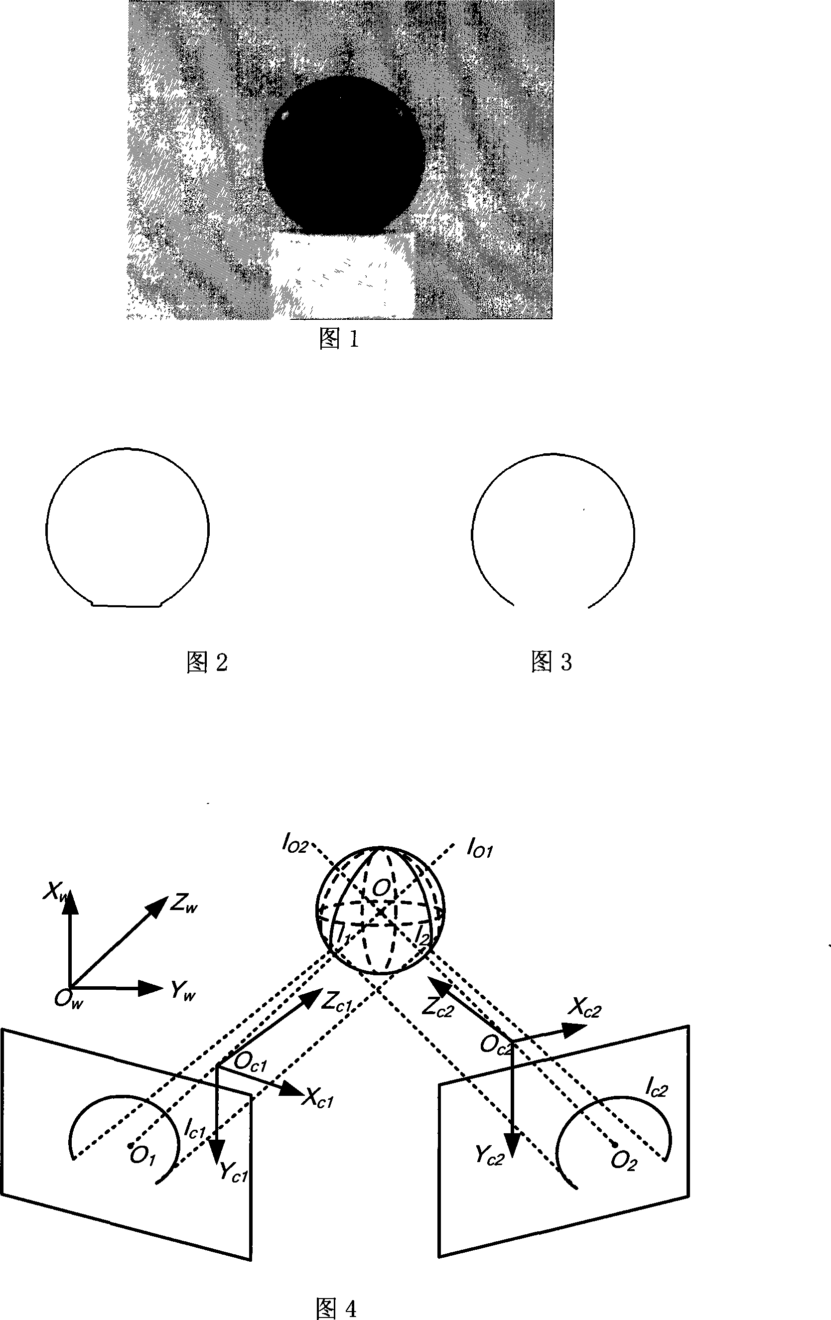
[0033] As shown in Figure 1, it is the spherical target required to calibrate the rotating shaft. The target uses a white column to support a black spherical target, and the background color is white for the convenience of target contour extraction.

[0034] 1) Acquisition of the edge of the spherical target

[0035] For the spherical target image, the gray value of the background is high, while the gray value of the spherical target is low, so the edge of the target can be roughly searched for by looking for pixels with gray value jumps, as shown in Figure 2. However, due to the influence of the base, this edge is not the real edge of the target, and the searched edges need to be screened. First, start from the highest point of the searched edge to pick out the edge along the searched edge to both sides, because this point is not affected by the base, it can be consi...


PUM


Abstract

The invention belongs to detection techniques with visual principle, particularly relates to a method for calibrating rotating shaft by binocular vision with convenient operation and simple calibration process. The technical proposal of the invention includes that the method for calibrating rotating shaft by binocular vision comprises the following steps of: (1) obtaining edge of a spherical target; (2) calculating the coordinates of the spatial spherical center; and (3) calibrating and calculating parameters of the rotating shaft. The invention measures the spatial characteristic points mainly by using two cameras to simulate the structure of human eyes.

Description

technical field [0001] The invention belongs to the technique of detecting by using the principle of vision, and in particular relates to a binocular vision rotation axis calibration method. technical background [0002] Binocular measurement technology is an important part of computer vision detection technology, which uses two cameras to simulate the structure of human eyes to measure spatial feature points. In order to expand the measurement range of the binocular measurement system, it is necessary to add a rotating table to the measurement system, so that the 360° measurement of the measured object can be completed. In order to ensure the accuracy of the measurement after the object under test rotates with the turntable, it is necessary to calibrate the turntable to find out the axis of rotation of the turntable. [0003] At present, the method of calibration of the rotating shaft in the computer vision measurement is mainly realized by a standard plane or a standard s...

Claims


Application Information

Patent Timeline
Patent Type & Authority Applications(China)
IPC IPC(8): G01B11/27G01B11/24G06T7/00
Inventor 王鹏孙长库
Owner TIANJIN UNIV
Learn More