Steel rail aligning mechanism and aligning method

A technology of rails and adjustment mechanisms, which is applied in the direction of track, track laying, track maintenance, etc. It can solve the problems of limited use functions and achieve the effect of prolonging the service life

Pending Publication Date: 2021-01-29
CRCC HIGH TECH EQUIP CORP LTD
View PDF1 Cites 0 Cited by
  • Summary
  • Abstract
  • Description
  • Claims
  • Application Information

AI Technical Summary

Problems solved by technology

Functionalit

Method used


Image

  • Steel rail aligning mechanism and aligning method
  • Steel rail aligning mechanism and aligning method
  • Steel rail aligning mechanism and aligning method

Examples


Embodiment 1

[0057] Embodiment 1.2: a rail alignment mechanism, the same as embodiment 1.1, the difference is that the twist adjustment oil cylinder 203, the horizontal adjustment oil cylinder 302, and the vertical adjustment oil cylinder 402 are replaced by power outputs such as geared motors, stepper motors, or leading screws device instead.

Embodiment 13

[0058] Embodiment 1.3: a kind of rail alignment mechanism, with embodiment 1.1, difference is: the guide groove of lateral guide chute 303, vertical guide chute 403, clamp rail mechanism 5 replaces with line rail or optical axis.

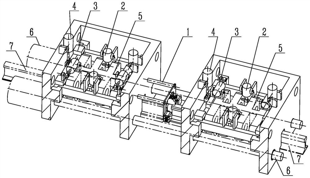
[0059] The above-mentioned rail alignment mechanism can automatically adjust the postures of the two rails to be welded to meet the selected rail alignment standard. It is used in rail welding equipment to realize the automatic alignment function of rails, thereby improving the efficiency and quality of rail welding, and the adaptability of existing welding machines. Reduce the workload of rail grinding in the later stage.

Embodiment 2

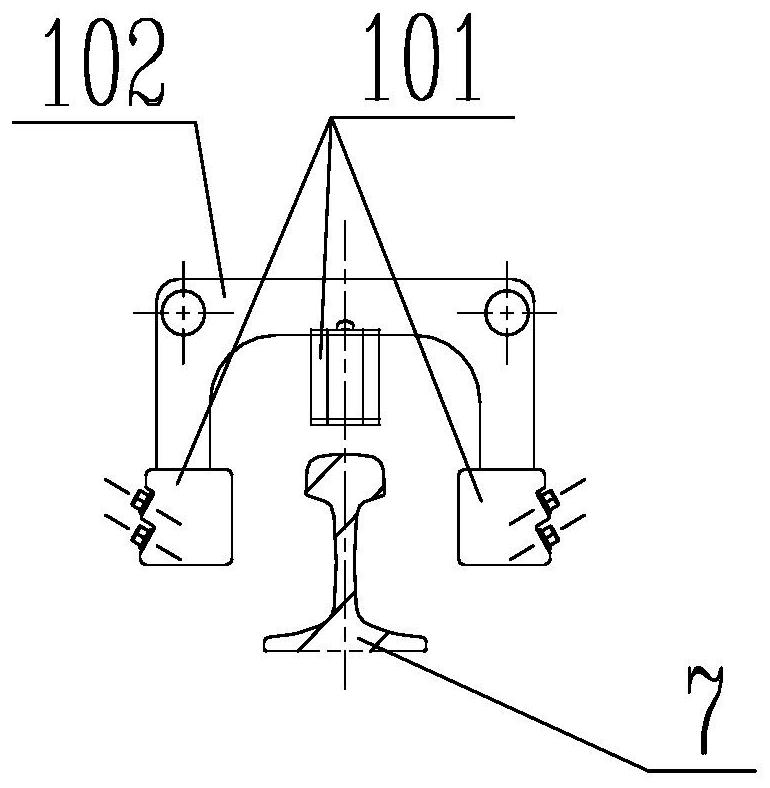
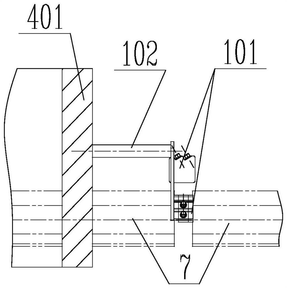
[0060] Embodiment 2.1: a rail-to-rail method, which includes placing the laser profile scanning sensor (101) on the top surface of the rail and the two sides of the rail respectively. The scanning sensor moving device (102) is fixed on the outer box (402); the scanning sensor moving device (102) drives the laser scanning sensor (101) to move in parallel to the direction of the rail (7) to scan and collect the position and profile data of the two rails. At the same time, it can stop at the joint of the two rails and monitor the alignment results of the rails in real time. The laser profile scanning sensor (101) feeds back the results to the rail attitude adjustment mechanism. The rail attitude adjustment mechanism compares the adjustment rules to obtain the required adjustment amount, and adjusts vertically or horizontally, or twists horizontally until the alignment of the rails meets the requirements. Require.


PUM


Abstract

The invention provides a steel rail aligning mechanism. The steel rail aligning mechanism comprises a steel rail profile scanning assembly (1), a steel rail torsion adjusting mechanism (2), a rail transverse adjusting mechanism (3) and a steel rail vertical adjusting mechanism (4). The whole steel rail aligning mechanism is installed between a rail clamping mechanism (5) and an upsetting mechanism(6) of rail welding equipment, after a steel rail (7) is clamped by the rail mechanism, the steel rail aligning mechanism starts to adjust the position of the steel rail, and disturbance errors caused by clamping the steel rail after alignment is completed are avoided. Steel rail alignment depends on sensor positioning. In this way, different steel rail alignment rules (such as steel rail centeralignment (8), steel rail bottom edge alignment (9), steel rail top surface alignment (10), steel rail right working edge alignment (11) and steel rail left working edge alignment (12)) can be used. And a welding machine structure or a welding machine rail clamping die structure is not changed. A rail clamping die is not needed to align the steel rail. The rail clamping die has no precision requirement, so that the service life is prolonged.

Description

technical field [0001] The invention relates to a rail alignment mechanism and belongs to the technical field of engineering equipment. Background technique [0002] At present, the clamping force of rail welding equipment widely used on railways is as high as 300 tons. The working principle of rail alignment is to use this feature to design the clamp as a high-precision positioning mold. Under the action of the clamping force, the two sections of rails are tightly attached to the clamping mold, and the alignment of the rails is completed depending on the precision of the clamping mold. Due to this feature, the existing rail welding equipment does not have a rail position adjustment function, and can only perform rail center alignment. When the positioning abrasive is worn, the rigidity of the welding machine body is reduced, the profiles of the two rails are inconsistent, the old and new rails are welded, and the alignment reference of the rails becomes the working edge, t...

Claims


Application Information

Patent Timeline
IPC IPC(8): E01B29/17
CPCE01B29/17
Inventor 吴玉祥刘亚南李军产
Owner CRCC HIGH TECH EQUIP CORP LTD
Why Eureka
Try Eureka