Refraction and reflection projection optical system

A projection optical system, catadioptric technology, applied in the field of projection optical system, can solve the problems of optical processing, optical inspection difficulties, lack of imaging quality data, size design restrictions, etc., achieve long working distance, correct aberrations, and reduce costs Effect

Active Publication Date: 2008-07-09
SHANGHAI MICRO ELECTRONICS EQUIP (GRP) CO LTD
View PDF1 Cites 14 Cited by
  • Summary
  • Abstract
  • Description
  • Claims
  • Application Information

AI Technical Summary

Problems solved by technology

[0004] However, the general projection exposure system expects a larger working distance and a shorter total optical length for the projection optical system.
However, in the five embodiments of the optical system given in the patent, the working distance only reaches the range of 7.5mm to 11mm, but the total optical length reaches more than 1150mm to 1200mm
Therefore, in the application of the actual projection optical system, the working distance will impose very strict size restrictions on the design of the workpiec

Method used


Image

  • Refraction and reflection projection optical system
  • Refraction and reflection projection optical system

Examples


Example Embodiment

[0035] The catadioptric projection optical system of the present invention will be described in further detail below.

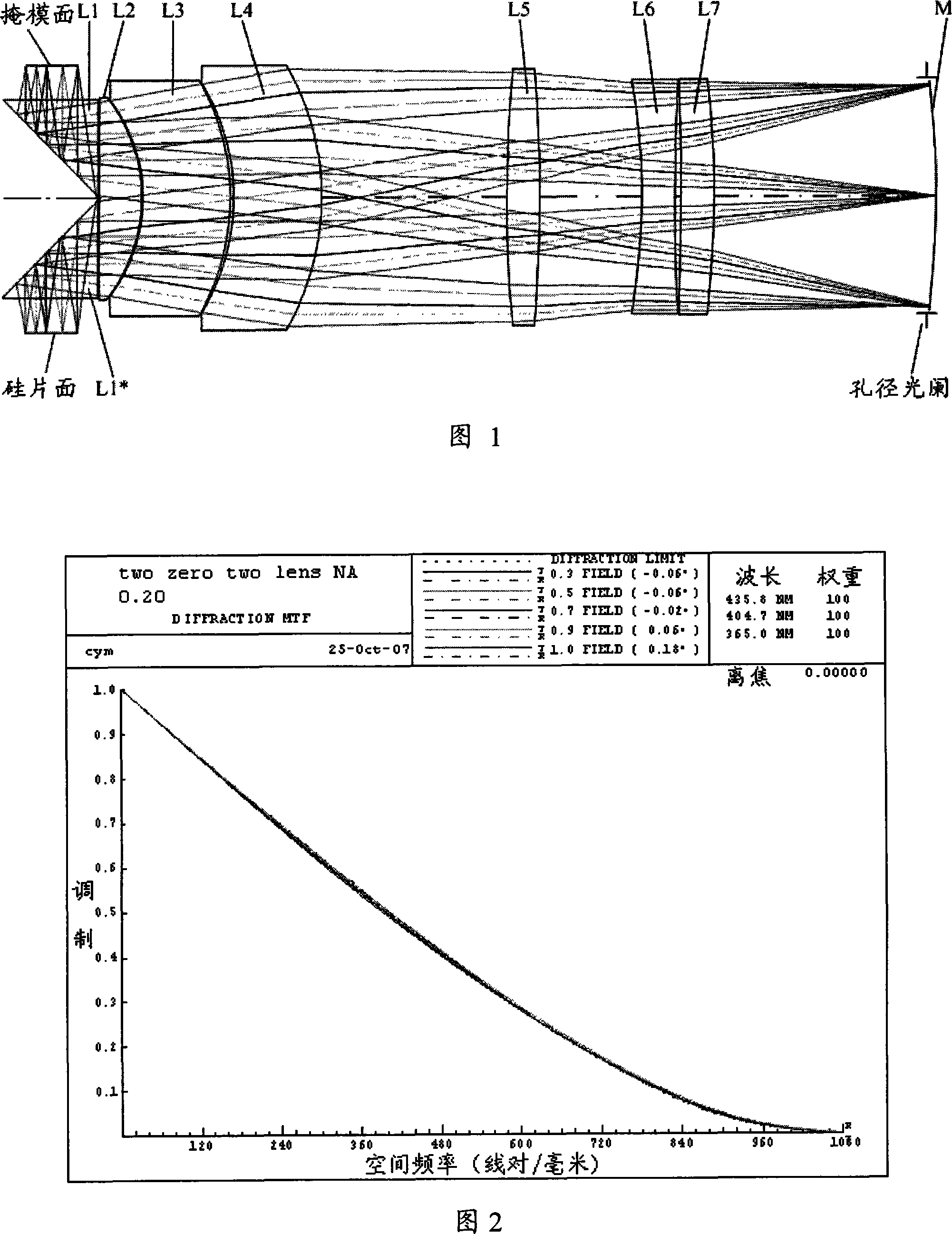
[0036] As shown in Figure 1, the present invention provides a catadioptric projection optical system, the projection optical system is a catadioptric symmetric structure, that is, from the side of the object surface sequentially includes a front (rear) group, provided with an aperture stop Concave spherical mirror M. Among them, under the light reflection of the concave spherical mirror M, the lens components of the front group are the common components of the rear group, that is, the optical structure of the optical elements shared by the front (rear) group is completely symmetrical (surface The radius and interval are equal, and the optical materials are the same), and the magnification is -1. The advantage of the symmetrical structure with a magnification of -1 is that according to the primary aberration theory, its vertical aberrations: coma, distortion, and ...


PUM


Abstract

The invention provides a diffractive-refractive projection optical system, which is used for projecting the image of a pattern disposed in an object plane into an image plane. The optical system sequentially comprises, along the optical axis direction, a front (rear) group and a concave-spherical reflector. The front and the rear groups share a common optical element group, which sequentially comprises, along the optical axis direction, a right-angled reflection prism, a first biconvex positive, a first meniscus thick lens, a second meniscus thick lens and a three-piece optical structure. An aperture diaphragm is arranged on the concave-spherical reflector to form a completely symmetrical structure with a -1 amplification rate of the projection optical system. Accordingly, the inventive diffractive-refractive projection optical system can effectively correct aberration and improve imaging quality; and can effectively shorten the total length of the projection optical system and achieve longer working distance.

Description

technical field [0001] The invention relates to a projection optical system, in particular to a catadioptric projection optical system used in related fields such as semiconductor lithography. Background technique [0002] With the development of projection lithography technology, the performance of projection optical system is gradually improved, and can be applied to various fields such as integrated circuit manufacturing. Projection lithography technology has been successfully applied to the field of sub-micron resolution integrated circuit manufacturing. At the same time, in semiconductor packaging technology, projection lithography technology is used to require lower High-yield gold bumps / tin bumps, wafer-level chip-scale packaging (WLCSP) technology and other fields, and for lower-resolution projection objective lens systems, there are continuous demands for improvement and performance improvement. [0003] In order to meet the requirements of the above-mentioned proj...

Claims


Application Information

Patent Timeline
IPC IPC(8): G02B17/08G02B1/02G03B21/00
Inventor 蔡燕民
Owner SHANGHAI MICRO ELECTRONICS EQUIP (GRP) CO LTD
Why Eureka
Try Eureka